This thread has been locked.

If you have a related question, please click the "Ask a related question" button in the top right corner. The newly created question will be automatically linked to this question.

how can I read data from bq34z100 I2C_write,I2C_read ?

Other Parts Discussed in Thread: BQ34Z100, BQEVSW, EV2400, BQ34Z110, BQ24450, BQ34Z100-G1, BQMTESTER, BQSTUDIO, BQPRODUCTION, GPCCHEM

Hi

Question:

Average current value of BQ34z100 from I2C - 1 byte data reads
Iteupnida very well.

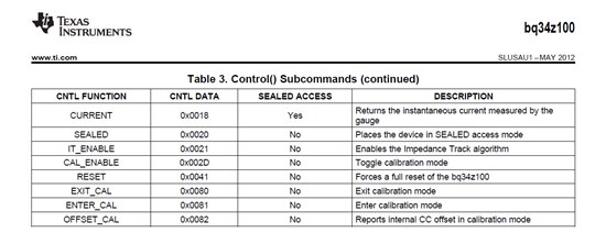
CURRENT: 0x0018 -> olryeogo to read the current value

Returns the instantaneous current measured by the gauge

Source program I2CCOMMAND (); Public get down Where Have
Questions Olympique stuffy feeling.
To a communication control microcomputer ATMEGA 128 reads the instantaneous value of current
Control () Subcommand address 0018 Read (); value 0xffff comes.
Dream, please let me know how to get favor.

Thank you very much.

 Example 1:

/ ------------------------------------------------ -----
/ / Pack_Voltage Reading
/ / ------------------------------------------------ -----
I2C_start ();
I2C_write (0xaa);
I2C_write (0x08);

I2C_start ();
I2C_write (0xab);
vt_l = I2C_read (1);
I2C_stop ();

I2C_start ();
I2C_write (0xaa);
I2C_write (0x09);

I2C_start ();
I2C_write (0xab);
vt_h = I2C_read (1);
I2C_stop ();

Tx_Pack [0] = vt_h;
Tx_Pack [1] = vt_l;


 / ------------------------------------------------ -----
/ / Pack_Current Reading
/ / ------------------------------------------------ -----
// Current 0x0018 Read       0X0000    ----- ?


I2C_start ();
I2C_write (0xaa);
I2C_write (0x00);
I2C_write (0x18); / / current
I2C_stop ();

I2C_start ();
I2C_write (0xaa);
I2C_write (0x01);
I2C_write (0x00);

I2C_stop ();


I2C_start ();
I2C_write (0xaa);
I2C_write (0x00);
I2C_write (0xab);
I2C_write (0x00);
ac_l = I2C_read (1);  --> Not  Read_Data  ?
I2C_stop ();


I2C_start ();
I2C_write (0xaa);
I2C_write (0x01);
I2C_write (0xab);
I2C_write (0x18);
ac_h = I2C_read (1);    --> Not  Read_Data  ?
I2C_stop ();

  • Arun,
    The gauge does not control the charging current. What caused the current to shut off and drop from 143mA to 0mA? Something terminated charging early.
    Tom
  • Hi Tom,

    Till now the problem related to Gas guage not solved.

    In control status RUP_DIS bit is set when update status is ox04.  Also the VOK bit is 0 , during the same condition. I tried with new fully charged battery, after discharging the battery to some level again i charged the battery,  same problem was there. for running optimization cycle only i did this. I am attaching the .gg file and log data along with this.  

    https://e2e.ti.com/cfs-file/__key/communityserver-discussions-components-files/196/data07.03.15.7z

    Regards,

    Arun Dev

  • Arun,

    Do you have a more complete log file. This one shows a partial discharge and a partial charge, but here are some comments.

    • It is common to see RUP_DIS set until the optimization cycle has completed.
    • The rest period between the discharge and charge is not long enough for a Qmax update. You need to rest until the OCVTAKEN flag has set.
    • It looks looks like the voltage measure issue has been fixed now.

    Please follow the procedure that I published earlier in this post very closely and collect log data through the entire process. If you reach the point where Qmax updates and it fails, then stop the process and send the log file to me. If Qmax does update, then proceed with the optimization cycle and also export a gg file every 10 minutes.

    Tom

  • Hi Tom, 

    One more query related battery voltage.  I am using bq24450 battery charger, its float voltage is designed for 13.8V, Boost voltage is 14.7V, Final discharge voltage is 10.5V. The new battery which i am using is reaching 13.6V Max. after that the current is getting to zero. If this is case which data in the Gas guage shud be changed.

    Practically Taper current is 140mA (Designed for 125mA). Here i am attaching the log data. How much time It is required for OCVTAKEN flag to get set.

    Should i remove the charger when current is reaching 0mA. i need to desolder the components when it reaches that point. Kindly do the needful. https://e2e.ti.com/cfs-file/__key/communityserver-discussions-components-files/196/08.03.15.7z

    Regards,

    Arun Dev N

  • Arun,

    It looks like you should set the Taper Current to 145 mA to make sure that it remaining long enough for a valid charge termination. I am not sure how long it will take for the OCVTAKEN flag to set. It could take a few hours, but it will timeout after 48 hours after charge and 5 hours after discharge.

    Tom

  • Hi TOM,

    Thank you so much for your valid time. Can you please go through the log data. In this also OCVTAKEN has not set after reaching full charge. At 13.6V my battery reaching the peak voltage. If this is the case how to change the values in register.

    charge.txt

    Regards,

    Arun Dev N

  • Arun,
    You probably need to let the pack rest longer to allow the cell voltages to stabilize. You waited for 1.5hours. The gauge will timeout and set OCVTAKEN after 48 hours, if the voltage has not stabilized.
    Tom
  • Hi TOM,

    The main problem  was because of the charger, i was using BQ24450 charger IC, it has temperature compensation because of that the voltage didn't reached the boost voltage. Its reference voltage changed due to temperature variation, now also i am using BQ24450.

    Here i am attaching the log data which i obtained in that VOK and QEN flag got set. I need to know any temperature compensation happens during guaging  also why RUP_DIS bit sets in some situation. With the above log data how can i go ahead.

    Thank you for your support, kindly do the needful.

    discharge+charge.log

    Regards,

    Arun Dev N

  • Arun,
    I checked the log data and the flags look normal. The VOK and QEN flags are set as they should be set and I did not see RUP_DIS set in the Control Status register.
    Tom
  • Hi TOM,

    After doing the above cycle which i have send to you, i did a small discharge, then i charged. The log data which i got with RUP_DIS bit set is attached along with this. why it happened ? also  i want to know during guaging any temperature compensation happens to reading?

    27.03.15.log

    Regards,

    Arun Dev N

  • Arun,
    The resistance update is disqualified until the pack has set a DOD point. The VOK should set and RUP_DIS should cleared when the discharge starts after the pack has rested until the OCVTAKEN flag has set.
    Tom
  • Hi TOM,

    Thank you so much.

    One important observation i have noticed is that , the gas guage is not reading the accurate state of charge(remaining capacity) of the battery on the load variation,

    Example,

    We are discharging fully charged battery with constant current  of  2 Amps and battery capacity reached to 20% (Voltage reached to 11.7Volts) and further we have reduced the load to 0.5Amps, in this condition voltage of the battery recovered to 12.1Volts but with this the capacity of the battery was not changed, it further starts reducing from 20% itself.

    But as per the battery datasheet, the capacity of the battery is determined by cell voltage and current load condition, let say suppose if we discharge at 2A,  the cutoff voltage is 10Volts and if the discharge current is 0.5Amps , the cutoff voltage is 10.5Volts. How we can program the gas guage to estimate the state of charge (remaining capacity) based on discharge current and Cell voltage. 

      Please do the needful.

    Thanking you,

    Regards,

    Arun Dev N

  • The simulation should increase SOC when the load current is reduced, if the Load Select is set to one of the "present cycle" settings. The gauge only runs FCC simulations at Ra grid points and after the temperature has changed by 10 degC.
  • Hi TOM,

    In the present cycle Load select was set to 1 only, sometimes SOC  is varying. I found that the new IC BQ34Z100-G1 has that feature. Kindly go through the below queries and reply me back.

    1. Other than .gg file,  what are the datas required for golden image.

    2. Procedure for golden image.

    3. How to program golden image, i am using Bq evaluation software, with that is it possible to program gas guage for final production.

    4. During charging SOC showing 100%, battery is not fully charged (update status 0x04).

    5. How to create .DFI file  and .ROM file

    6. How to make BQ multi station tester.

    Regards,

    Arun Dev N


  • Arun,

    Here is a response for the bq34z100 and bq34z100-G1.


    bq34z100

    1. Other than .gg file,  what are the datas required for golden image.

    [TEC]   The golden image is created after loading the default senc file, the ChemID and the golden gg file in that order.

    2. Procedure for golden image.

    [TEC]   After the files have been loaded (see #1), then export a .rom file using bqMtester.

    3. How to program golden image, i am using Bq evaluation software, with that is it possible to program gas guage for final production

    [TEC]   The .rom file cannot be imported using the bqEVSW. You can use bqMtester or you own custom tool. The Going to Production document provides example code to export and import .dfi files.

    4. During charging SOC showing 100%, battery is not fully charged (update status 0x04).

    [TEC]  This could occur if the optimization cycle has not been completed. After Qmax and Ra table have been update, SOC reporting should be accurate. This could also occur, if a reset occurs and the gauge makes a capacity estimate based on the OCV table, but it will be corrected after the pack has been fully charged.

    5. How to create .DFI file  and .ROM file

    [TEC]  See Items 2 and 3.

    6. How to make BQ multi station tester.

    [TEC]  The bqMtester hardware does not support the bq34z100, but you can use the bqMtester program to update and calibrate the gauge.

    bq34z100-G1

    1. Other than .gg file,  what are the datas required for golden image.

    [TEC]   The golden image is created after loading the default srec file, the ChemID and the golden gg.csv file in that order.

    2. Procedure for golden image.

    [TEC]   After the files have been loaded (see #1), then export a .srec file using bqStudio.

    3. How to program golden image, i am using Bq evaluation software, with that is it possible to program gas guage for final production

    [TEC]   The golden srec can be programmed into a device using bqStudio or bqProduction. bqProduction also offers the option to just import the data flash portion of the srec to speed up the process. b

    4. During charging SOC showing 100%, battery is not fully charged (update status 0x04).

    [TEC]  This could occur if the optimization cycle has not been completed. After Qmax and Ra table have been update, SOC reporting should be accurate. This could also occur, if a reset occurs and the gauge makes a capacity estimate based on the OCV table, but it will be corrected after the pack has been fully charged.

    5. How to create .DFI file  and .ROM file

    [TEC]  These file formats are not supported by bqStudio or bqProduction. You can still use the dfi process to export and import the data flash, but you will have to use you own tools.

    6. How to make BQ multi station tester.

    [TEC]  The bqMtester hardware and program do not support the bq34z100-G1. You can use bqProduction to communicate with your module over the I2C bus and program and calibrate your pack.

    Tom

  • Hi TOM,

    Thank you so much, Now i got a clear idea how to use. I need some help from you,

    1. I tried to download BqMtester software but it failed, can you send me the software. (mail id:  arun.dev@skanray.com).

    2. Currently i am using bq34z110, i didn't got the new IC Bq34z100-G1. The default .senc file of that IC (bq34z110), i didn't have , can you provide it.

    3. Should i need to buy BqMTester hardware or not. 

    Kindly go through the procedure which i understood and correct me if any steps is not correct.

    1. BqMTester software + EV2300 + gas guage interface is required for exporting and importing the .ROM file. 

    2. After completing the 2 Charge /Discharge cycle of the battery ,export the data flash using BQ evaluation software and change the update status to 0x06  and FC set % to 100.

    3. After 2 nd step write the data flash to gas guage using   BQ evaluation software.

    4. Export the .ROM file of the above gas guage using BqMtester software.

    5. The above exported .ROM file is Imported to all other gas guage used for production.

    Kindly do the needful, I am very much thankful for the support provided by the TI.

    Regards,

    Arun Dev N

  • 1. I tried to download BqMtester software but it failed, can you send me the software. (mail id:  arun.dev@skanray.com)

    [TEC]  I will send you a link to download the setup file.

    2. Currently i am using bq34z110, i didn't got the new IC Bq34z100-G1. The default .senc file of that IC (bq34z110), i didn't have , can you provide it.

    [TEC]  I attached the default senc file.

    3. Should i need to buy BqMTester hardware or not. 

    [TEC]  The bqMtester hardware does not support the bq34z110. You can use the bqMtester program with your module.

    Kindly go through the procedure which i understood and correct me if any steps is not correct.

    1. BqMTester software + EV2300 + gas guage interface is required for exporting and importing the .ROM file


    [TEC]  correct

    2. After completing the 2 Charge /Discharge cycle of the battery ,export the data flash using BQ evaluation software and change the update status to 0x06  and FC set % to 100.

    [TEC]  After the optimization cycle has completed, then you can export the gg file and set Update Status to 02 and both Cycle Count parameters to 00. I normally leave FC Set = -1.

    3. After 2 nd step write the data flash to gas guage using   BQ evaluation software.

    4. Export the .ROM file of the above gas guage using BqMtester software.

    [TEC]  Import the default senc file, the ChemID and the updated golden gg file. Then export the golden .rom file.

    5. The above exported .ROM file is Imported to all other gas guage used for production.


    [TEC]  The golden .rom file can be imported to production packs, then calibrate the pack, send the IT Enable and the seal the pack. It is then ready to be shipped.

    Kindly do the needful, I am very much thankful for the support provided by the TI.

  • Hi TOM,

    Thank you so much, 

    Can you send me the BqMtester software   and default   .senc file of bq34z110. ( mail ID : arun.dev@skanray.com) , when i tried the  link (www.ti.com/.../slvc107c.zip}  it is showing web page not available.

    In bqChem the manufacture name of my battery not there, can you provide support for that. 

    Regards,

    Arun Dev N

  • Here is the default senc file.

    https://e2e.ti.com/cfs-file/__key/communityserver-discussions-components-files/196/6201.bq34z110_5F00_V0_5F00_04_5F00_BLD_5F00_0004.senc

  • Hi TOM, 

    Thank you,

    I am facing the below problems,  when i open the software. 

    1. When i opened Bq Tester ROM Imager - Auto detect , it is showing "Communication error reading from gas guage".

    2. When i opened Bq Tester ROM Imager - Bq34z110-v0.01, it is showing "unsupported target".

    3. In Bq Tester station set up, it showing "lock status".

    With the same connection by using Bq Evaluation software, i am able to read all contents.  Kindly do the needful.

    Regards,

    Arun Dev N

  • Arun,

    Sometimes Auto-detect does not work and you have to select the device from the pull-down list. You should select the bq34z110 v0.04.

    There is no password. Just press OK to proceed.

    Tom

  • Hi Tom,

    1. when i opened, Bq Tester ROM Imager, from pull down list i selected bq34z110 v0.01, it is showing unsupported target.

    2. Can you send the latest ev2300 driver software, i updated my driver which you have provided in the link " (  https://e2e.ti.com/support/power_management/battery_management/f/180/t/128220" 

    3. When i open multi station tester software, it is showing error: expected 1 board, found 1. after that the window is automatically closing.

    Please do the needful

    Regards,

    Arun Dev N

  • The bq34z110 v0.04 device should be shown in the list, if you copied the config and target files to the bqMtester directory. the instructions were in the readme file. Here they are, in case you need them.

    2235.config.zip

  • hi Tom,
    sorry for the mistake, thank you.

    Regards,
    Arun Dev N
  • Hi TOM,

    Thank you so much for your great support, 

    Here i am attaching the Log data of one optimization cycle i did,

    1.During charging battery capacity showed above 5000mAH. 

    2. With this data, can you provide the Chem ID of my battery ( lead acid valve regulated battery).

    3. is this cycle ok.

    Discahrging 1st step.logcharging 2 nd step.logdischarging 3rd step.log

    Regards, 

    Arun Dev N

  • Arun,

    The Mathcad program could not find a ChemID match. The rest periods are not long enough. Please use the attached document for guidance and log data thoughout the entire process.

    Tom

    6237.Chemistry selection.pdf

  • Hi TOM,

    I have some query related to gas guage Bq34z110.

    1. I didn't have HDA169 calibration board, how can i dump .ROM file to gas guage using Multi station Tester.

    2. Without HDA169, During  production can i calibrate using bq evaluation software or how to calibrate with Multi station Tester.

    3.  Without .ROM file , can i go ahead with the below procedures for going to production using bq evaluation software,

        a)  After completing optimization cycle save .GG file ( update status 02).

        b) Program  the gas guage with .SENC file.

        c) Import .GG file (Update status 06).

        d) Calibrate the voltage and current.

        e) Use it as the final package in product.

    Kindly do the needful.

     Regards,

    Arun Dev N

  • Arun,
    You can use the bqTester ROM Imager to export a .rom file without using the bqMtester hardware. You can calibrate using the bqEVSW without the bqMTester hardware or calibrate using the bqMester hardware and program.
    Tom
  • Hi Tom,

    Thank you, by using imager .rom file is exported. To import .ROM , i used bq tester set up.exe software, while pressing save configuration and close, the window closes.

    is this the correct way to import .ROM file to gas guage or any other way. 

    Regards,

    Arun Dev N

  • Using the bqMtester program is the correct method to program a .rom file. I tested the single station and multi-station programs and was able to program the .rom file with both of them without having to use the bqMtester hardware.
  • Hi Tom,

    To import the .ROM file i have confusion,

    The procedure which i understood i am writing below, correct me if i am wrong,

    1. Take the .ROM file by using imager.

    2. Open Multi station set up.

    3. unlock, search for connected device, save and proceed, Next.

    4. In Global configuration window, In update data flash  Image, put the .ROM file by Browsing.

    5. Save configuration and close.

    6. Open Multi station Testing, Press Start.

    This much procedure is enough for importing the .ROM file. Please do the needful.

    Regards,

    Arun Dev N

  • Arun,

    That procedure should work. Do you receive any errors?

    Tom

  • Hi Tom,

    Thank you, i didn't got any errors. When gas guage was not connected Muti station tester showed error.

    Can you tell me through which software window (Out of the 3 BQ tester windows) ,the .ROM file will be loaded to Gas guage.

    Regards,

    Arun Dev N

  • Hi tom,

    I started using New gas gauge BQ34Z100-G1, in that while calibrating voltage it is showing error

    "cell voltage correction beyond allowed range". i am attachin the .gg file of it. i am using lead acid battery (12V, 6 cell).

    please do the needful. 

    data 29.07.15.zip

    Regards,

    Arun Dev

  • Arun,
    I did not receive the attachment. I assume that you are using bqMtester? If so, you should have the program load am srec file that contains calibration data from the golden pack. The bqMtester program only allows a certain amount of change in the calibration parameters or it issues a warning.
    Tom
  • Dear TOM ,
    I started using the New gas guage Bq34z100-g1 , replacement to bq34z110. I am using bq studio software. i attached the .gg file above. Can you provide .srec file for that.
  • Arun,
    We do not have a tool to import the parameters from the z110 into the z100-G1. They have to be entered by hand into the data flash in bqStudio. I am not going to have the time to do this for you, but there are not a lot of them that will have to change.
    Tom
  • Hi,

    [ss] isn't just a small bit in the "Control Status" register? So, what is the value 36720414 about?

    Thanks a lot.

    Vítor Pereira

  • Tom,

    I have some queries related to bq34z110,

    1) if load mode = 2, what value gas gauge will consider.

    2) if load select= 1 and load mode= 2, how gauging will happen.

    3) if load mode required to be changed, optimization has to repeat?

    Regards, Arun

  • The [SS] bit indicates that the gauge is in Sealed mode. The value 36720414 is the default unseal code.
  • Load Mode = 2 will revert to Load Mode = 0

    You will not have to rerun the optimization cycle if you change the Load Mode or Load Select.

  • TOM,

    Thank you, i have some query related to golden image data in production line.

    1) After programming the golden image, the update status shall change to 0x06 or not.

    2) If update status is 0x06, the IT enable command shall be sent to gas gauge or not

    3) At the final stage of golden image programming, the update status shall be set to which value and IT enable command shall be sent or not?

    4) How the Q MAX value will get updated?

    Kindly do the needful..

    Regards,

    Arun Dev

  • The Update Status should be set to 02 in the golden file, so that it will go to the 06 state after the IT Enable command has been sent. You should not send the IT Enable command until after you have calibrated the pack and updated any pack specific parameters in the data flash. You can then send the IT Enable and Seal commands. Qmax and the Ra tables are updated as the pack is used. The Ra tables are update during discharges and Qmax is updated during rest periods after qualified charges and discharges. Qmax is only updated in the rest period after discharges for NiMH and PbA cells.
  • Tom,

    I have some queries regarding bq34z110.

    1) Can i use .gg file in production instead of .dfi /.Rom file.

    2) What and all extra parameters present  in .Rom file compared to .gg file.

    3) Can we use .senc file instead of .Rom in production.

    4) Instead of sending IT enable command, can we directly change the update status register to 06.

    5) If a short term high current consumption is there, Did Fast conv bit can help to predict the the SOC?

    6) We are observing a current offset of 40mA in one field returned unit, when i reprogram  the default  .senc file and .gg file the offset has gone. For the faulty .senc file is programmed again the offset reappears.

    Kindly do the needful.

    Regards,

    Arun Dev

  • Arun
    You cannot use a gg file to program packs in production, because it does not contain the chemistry parameters. You can use a .rom. dfi or .senc file as these contain all of the necessary data. The .rom and .dfi files contain the data flash and the .senc contains the full flash. (DF plus IF)

    You should not enable IT in the golden file, because you need to calibrate the pack before sending the IT Enable.

    I am not sure what you are referring to with the Fast Convergence comment. This feature helps with simulations near the end of discharge.

    the 40mA is probably due to the CC Offset parameter. The gauge will run CC Offset calibrations to compensate for offsets that occur from temperature changes. It runs these when the gauge enters the standby state.

    Tom
  • Tom,

    Thank you so much. 

    1) .Senc file contain DF plus IF , so is it the best suitable file for final programming compared to .Rom and .DFI .

    2) Is it mandatory to do Board offset calibration and CC offset calibration to all individual packs.

    3) We have a .Senc file, in that an offset of 40mA is shown in current reading, i will share that file with you. 

    4) Kindly help us to find why that problem has come and because of what. If we change the .gg file, there is  no impact on offset.

    5) I need your help to find the chem ID. I am sharing the log data of battery charge discharge cycle.

    Kindly do the needful.Gas gauge data.zip

    Regards, 

    Arun Dev

  • I tried programming CC Offset and Board Offset numbers from your gg file into a pack and I do not see a 40mA current reported. the device is either defective or there is a bard offset on that board.

    I checked you log data with the GPCCHEM tool and it predicts ChemID 800 to be an acceptable match to your cells.
  • Tom,

    Thank you so much.

    1) For an actual current of 0mA , gas gauge is showing 40mA for that particular .senc file. I am again attaching the .Senc file

    Related to optimization cycle i have few queries,

    2) While running optimization cycle shall we enable sleep mode ?

    3) If sleep mode is enabled whether gas gauge will enter relaxation mode.

    4) What shall be the values of  Cell0 R_a flag & xCell0 R_a flag , we are using 0x0555 & 0xFFFF, is it right?

    5) What shall be the values of Max sim Rate and Min sim Rate , our battery spec is 5AH , 12V( 6cells).

    kindly do the needful.4784.Gas gauge data.zip

  • Arun
    Thi is the same enc file that I checked off-line and found the data flash to be corrupted. The parameter that is causing the Current to read 42mA is the CC Max Offset sample.

    You can have Sleep mode enabled when running the optimization cycle and this does not affect relaxation.

    The 0555 indicates that the Ra table update is in progress, but not complete. It will be 0055 after Qmax has updated in the relaxation period.

    The Min Sim Rate should be set to 20 and the Max Sim Rate should be set to 0.

    Tom
  • Tom,

    Thank you,

    1) Because of what  CC MAX Offset can get corrupted.

    2) What preventive measure we can take in production to avoid above problem.

    3) If i am not sending IT enable manually also QEN flag is getting set. Why that is happening

    4) If QEN flag is set , whether that shows IT is enabled ?