This thread has been locked.

If you have a related question, please click the "Ask a related question" button in the top right corner. The newly created question will be automatically linked to this question.

how can I read data from bq34z100 I2C_write,I2C_read ?

Other Parts Discussed in Thread: BQ34Z100, BQEVSW, EV2400, BQ34Z110, BQ24450, BQ34Z100-G1, BQMTESTER, BQSTUDIO, BQPRODUCTION, GPCCHEM

Hi

Question:

Average current value of BQ34z100 from I2C - 1 byte data reads
Iteupnida very well.

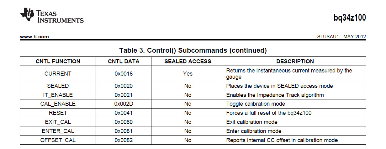
CURRENT: 0x0018 -> olryeogo to read the current value

Returns the instantaneous current measured by the gauge

Source program I2CCOMMAND (); Public get down Where Have
Questions Olympique stuffy feeling.
To a communication control microcomputer ATMEGA 128 reads the instantaneous value of current
Control () Subcommand address 0018 Read (); value 0xffff comes.
Dream, please let me know how to get favor.

Thank you very much.

 Example 1:

/ ------------------------------------------------ -----
/ / Pack_Voltage Reading
/ / ------------------------------------------------ -----
I2C_start ();
I2C_write (0xaa);
I2C_write (0x08);

I2C_start ();
I2C_write (0xab);
vt_l = I2C_read (1);
I2C_stop ();

I2C_start ();
I2C_write (0xaa);
I2C_write (0x09);

I2C_start ();
I2C_write (0xab);
vt_h = I2C_read (1);
I2C_stop ();

Tx_Pack [0] = vt_h;
Tx_Pack [1] = vt_l;


 / ------------------------------------------------ -----
/ / Pack_Current Reading
/ / ------------------------------------------------ -----
// Current 0x0018 Read       0X0000    ----- ?


I2C_start ();
I2C_write (0xaa);
I2C_write (0x00);
I2C_write (0x18); / / current
I2C_stop ();

I2C_start ();
I2C_write (0xaa);
I2C_write (0x01);
I2C_write (0x00);

I2C_stop ();


I2C_start ();
I2C_write (0xaa);
I2C_write (0x00);
I2C_write (0xab);
I2C_write (0x00);
ac_l = I2C_read (1);  --> Not  Read_Data  ?
I2C_stop ();


I2C_start ();
I2C_write (0xaa);
I2C_write (0x01);
I2C_write (0xab);
I2C_write (0x18);
ac_h = I2C_read (1);    --> Not  Read_Data  ?
I2C_stop ();

  • Shin

    Here is the sequence for using Read/Write I2C byte commands to read the Current (0x0018)control subcommand.

    Using "Read/Write I2C Byte"

    enter    I2CCommand 00  Byte  18   press    Write Byte button                              (The scope waveforms occur in this order. AA, 00, 18)

    enter    I2CCommand 01  Byte  00   press    Write Byte button                              (The scope waveforms occur in this order. AA, 01, 00)

    enter    I2CCommand 00   press    Read Byte button; GUI returns a 00                (The scope waveforms occur in this order. AA, 00, AB, 14)

    enter    I2CCommand 01   press    Read Byte button; GUI returns a 01                (The scope waveforms occur in this order. AA, 01, AB, FE)

    This will be FE14 or -491mA.

    Regards
    Tom

  • Hi Tom

    Issuing the command as you said, in part due to my mistake.
    Is now a well I2CCOMMAND ().
    Very grateful.

    I have one question.
    SOC values ​​sometimes the data value to 0%, as is indicated.
    Then when you load the SOC values ​​return to normal.
    I do not know what these other symptoms occur.
    I think the cause may 0x0041 RESET () command to initialize the
    I would like to ask what often

    Or cause you do not know whether the communication failure occurs do you think. ?

    Have a nice day like to ask a good answer ...

    I'm very much obliged to you.

    SHIN

  • Hi Tom

    Very prospers reads 0x0018 current.

    Charge and discharge three times last hop part now, the SOC value've jalmat.
    The initial power on bq34z100 input and setting after discharge sikyeoseo
    Went to 100% SOC values ​​dropping to 0% SOC values ​​continue to discharge if
    99% to 30% will go down.
    Battery Power Remaining are not accurate. ?

    When you load the pack voltage is 3.0V or less continue to discharge
    From 0% to 100% SOC values ​​regress.
    So the initialization command RESET 0X0041 down the SOC values
    0% back to normal. Omnida.
    Seal to Unseal to go into the mode as follows: When Will the microcomputer?
    Or Do you have any other way


    Example 1 :

    seal to unseal micom controll 

    1)   ss  :   36720414 

    2)   fas :   ffff ffff

     (The scope waveforms occur in this order. AA, 00, 14)   press

     (The scope waveforms occur in this order. AA, 01, 04) press

     (The scope waveforms occur in this order. AA, 00, 72) press

     (The scope waveforms occur in this order. AA, 01, 36) press


     (The scope waveforms occur in this order. AA, 00, ff) press

     (The scope waveforms occur in this order. AA, 01, ff) press

    (The scope waveforms occur in this order. AA, 00, ff) press

     (The scope waveforms occur in this order. AA, 01, ff) press

  • Shin,

    I looks like you have the pack gauging, but not perfectly. There are some steps required to insure accurate gauging.

    1) The device parameters must be setup properly.

    2) The proper ChemID for the batteries must be loaded in the device.

    3) The device must be calibrated.

    4) Impedance Track must be enabled. Enter 21 <enter> in the Control field on the DataRAM screen.

    5) You must run a learning cycle on the pack to calibrate Qmax and the Ra-table.

    Have you completed all of these steps? You can send me a .gg file and I can check it for potential problems. You can save a .gg file by going to the Data Flash page.

    1) Press the Read button to populate the table.

    2) Go to File > Export and save the .gg file onto your computer. You can attach this file to this message string.

    The process looks correct to unseal the device, but I would not seal it until everything has been setup and is working properly. Unfortunately, you cannot keep it unsealed, if the seal command has already been sent. You will have to reload the Instruction Flash program to disable seal mode. I attached the .senc file to help you do this. To initialize the device back to the brand new state.

    1) Download the .senc file.

    2) Disable "Keep Scanning" on the DataRAM screen, if it is enabled.

    3) Save the gg file, if you have already made changes to the Data Flash screen and you want to import those changes back into the device. (This will not seal the device.)

    4) Go to the I2C Pro screen.

    5) Use the "Write I2C Data Block" field to put the device into ROM mode. I2C Com and 00 DataBlock 000f.

    6) Use the "Programming" field. Search for the .senc file. Press the Program button. A pop-up window should appear with downloading progress. DO NOT STOP THE DOWNLOADING PROCESS ONCE IT HAS STARTED. It may damage the device, if you do stop it in the wrong place.

    7) Close the pop-up window after it has completed. Press the Execute button to return the device to normal mode.

    The device is now in a new state. You can reload your gg file and ChemID to proceed.

    To load the gg file.

    1) Go to the Data Flash screen.

    2) Go to File > Import. Find your file and load it.

    3) Press the Write All button to save the data into the flash.

    3) Go to the DataRAM screen.

    4) Enter the 41 command in the Control field <enter>  to reset the device and transfer data from flash to RAM.

    5) Enter the 21 command in the Control field <enter> to enable Impedance Track.

    I hope that this helps.
    Tom

    bq34z100_v0_06.senc
  • Tom,

    4) Impedance Track must be enabled. Enter 21 <enter> in the Control field on the DataRAM screen.


    I don't see the Control Field in the DataRam screen.   How to I enable IT?   Do I need to do it via the I2C screen, or am I missing something?


    - Ross

  • Ross

    Does this help?

    Regards
    Tom

  • Yes thank you --  I did not realize that you could do writes from there..   I ended up doing it with I2C page but this info will be helpful in the future.

    Thanks - Ross

  • ThomasCosby said:

    Shin

    Here is the sequence for using Read/Write I2C byte commands to read the Current (0x0018)control subcommand.

    Using "Read/Write I2C Byte"

    enter    I2CCommand 00  Byte  18   press    Write Byte button                              (The scope waveforms occur in this order. AA, 00, 18)

    enter    I2CCommand 01  Byte  00   press    Write Byte button                              (The scope waveforms occur in this order. AA, 01, 00)

    enter    I2CCommand 00   press    Read Byte button; GUI returns a 00                (The scope waveforms occur in this order. AA, 00, AB, 14)

    enter    I2CCommand 01   press    Read Byte button; GUI returns a 01                (The scope waveforms occur in this order. AA, 01, AB, FE)

    This will be FE14 or -491mA.

    Regards
    Tom

    Thank you Tom, I can confirm this works 100%

  •  hi ,

     I am facing the same issue as you faced. I am getting 0xffff as reply from gas guage IC.

    The sequence i am using,

    Start , 0xAA ,0x00,0x08,stop

    Start , 0xAA, 0x01,0x00,stop.

    start, 0xAA ,0x00,0xAB, after that I am getting "FF" as reply from IC. can you help me.


    Regards,

    Arun Dev

  • Arun, 

    Here are some scope waveforms showing the byte transfers. I was using the EV2400 and the bqEVSW to send the commands. 

    Tom

  • Hi Tom,

    I saw the waveform, some problem i found in my I2C channel.

    problem (Start ,0xAA, 0x00  after that Data line is going low for  5.2us  ) any delay i need to maintain in between data.

    I have one doubt, the first 2 byte (Data) in your waveform going at the same clock.

    Actually 1 byte at a time in I2C communication.?

    Is it possible to dump golden image without EV2300 / EV2400 ?

    Regards,

    Arun Dev

  • Arun, 

    The device does support auto-increment, so you do not have to use the byte transfer mode. I am not sure whether this is what you were asking with your question. You can also transfer the golden file without the EV2300 and TI tools. There are some guidelines our Going to Production applications report. SLUA665

    Tom

  • Hi Tom,

    Thank you, my question is 0xAA and  0x00 both coming in the same clock (In the  first waveform you have sent ).

    Regards,

    Arun Dev N

  • Hi Tom,

    Really i am stuck with this Gas guage IC.

    I already mentioned you I am using New IC, any initialization is required.

    when I send 

    Start, 0xAA , 0x00 ,  Restart, 0xAB i am getting reply ' FF '.  When i change the command also 'FF' is coming. The  document which you had sent to me was too good. But I tried that sequence no Response.

    Kindly do the needful. Project is on end stage. 

    Regards,

    Arun Dev


  • Arun,

    Have you tried the bqEVSW and the EV2300 to communicate to the device. If not, you should try this and compare the waveforms. There has to be a difference in the setups.

    Tom

  • Hi Tom,

    OK i will try with EV2300. Why 'FF' is coming ? Any suggestions for that. Any problem with frequency ?

    Regards,

    Arun Dev

  • Arun,

     What frequency are you using for the I2C clock? The device can support up to 400 KHz. Can you provide a scope capture for the case where it is returning FF? The FF may get returned, if the device is not ready to be read.


    Tom

  • Hi TOM,

    Sir  i will send the waveform which i have got.

    Today i tried the sequence

    START , 0xAA , 0x0e , Restart , 0xAB ,  i got reply 2 bytes (0x06, 0x18 ) is it correct.

    For the sequence you have suggested now I am getting 0x00.

     START , 0xAA , 0x00 ,0x08 ,  STOP

    START , 0xAA , 0x01 ,0x00 ,  STOP

    START , 0xAA , 0x00 , Restart , 0xAB,   i am getting reply as  0x00  .

    Regards ,

    Arun Dev N

  • Hi TOM,

    For the command MFR Name , i am getting the reply Texas Ins like that. Also for the sequence 

    START ,0xAA , 0x00 , 0x08 , STOP

    START , 0xAA , 0x01 , 0x00 , STOP

    START , 0xAA , 0x00 , 0xAB  

    I am getting reply  0x7E and 0x0D. Is it correct.  Actually i made a small delay after 2 byte transmission.

    For SOC I am getting 0. How we need to initialize ?

    Thank you for your support.

    Regards,

    Arun Dev N

  • Hi TOM,

    Thank you for your support, Gas guage IC is replying. Your waveform file helped me alot to rectify the problem. 

    I ordered one EV2300 , One doubt i have , for state of charge ,Remaining capcity, full charge capacity .....etc.


    It is replying '0' value. I didn't enabled IT_ENABLE, actually i am using one new IC. How can i dump Golden image with controller alone. 

    Regards,

    Arun Dev N

  • Arun,

    You cannot export the .gg file without using the TI tools, but you can export a .dfi file. The .dfi file contains the full data flash and an example of the process can be found in the Going to Production document. Search for SLUA665 on the TI website.

    Tom

  • Tom,

    If i dump that  file ,then only the IC will give the Value for 

    state of charge ,Remaining capcity, full charge capacity .....etc.


    I gone through that document i didn't under stood anything. Can you help 

    Now i have only controller to interface this IC.

    Regards,

    Arun Dev


  • Arun,

    The SOC, RemCap and FCC are not stored in the data flash. They are calculated parameters and are only stored in RAM. I am not sure how much guidance I can provide beyond what we provide in the document. We are not setup to provide support for customer specific communications platforms.

    Tom

  • I didn't had much trouble at all addressing the device and get it to work.

    What platform are you using?

  • Tom,

    Based on what it start calculating ? what input i need to give to the IC.

    Regards,

    Arun Dev

  • Hi Tom,

    I had bought EV2300 and BQ34Z110 Evaluation board.

    I have connected EV2300 and bq34z110 evm board, i am getting SOC and charge voltage in DATA RAM software tool. With this all are ok.

    then i have connected EV2300 and my hardware circuit containing Gas guage IC , i am getting ZERO value for  SOC and charge voltage in DATA RAM software tool. Some time control status reg: switches from

    ( 0x0014 to 0x0004 ) also control reg : value (0x0005 to 0x0006)

    How can i edit DATA RAM using software tool. I feel may be the EVM board is actually calibrated one so that it is giving SOC. Can you provide any default file that can be programmed to my hardware to make it working.

    Regards,

    Arun

  • Arun, 

    There is probably a mismatch between your ChemID and your cells causing the 0% SOC issue. Please log a full discharge using the guidelines in the attached document. Then export a senc file and send this two files to me. I will check to see whether you are using the proper ChemID and I will also check your configuration. 

    Tom

    Chemistry selection.pdf
  • Hi Tom,

    Some details other than the discharge cycle of the battery is attached along with this.

    Data flash file(.gg format) ,Data RAM (text format) , Battery datasheet (lead acid) .

    I will send the discharge cycle document on tomorrow, Can you look at the documents and suggest the modification if any.

    Regards,

    Arun Dev N5531.Bat - SLA - CP1250 - Vision.pdf

    bq EVSW Version: 0.9.90 for bq34z110 v0.04	
    Device:110,Ver:0.04
    10/26/2014 4:24:49 PM	
               
    Sample	Stamp	~Elapsed(s)	Control	CtrlStatus	StateofCharge	RemCap	FullChgCap	Voltage	AveCur	Temperature	Flags	@Rate(@)	@TimeEmpty	NomAvailCap	FullAvailCap	AvgTimeEmpty	AvgTimeFull	StandbyCurr	StandTTE	MaxLoadCurrent	MaxTTE	AvailEnergy	AvailPower	TTEConstPwr	IntTemp	CycleCnt	StateofHealth	Charge Voltage	Charge Current	Passed Charge	DOD0	SelfDischargeCurrent	PackConfig	Current
    1	4:25:01 PM	0	0004	0004	0	0	3454	0	5	-39.2	1806	0	65535	0	3454	65535	41280	-10	0	-500	0	0	0	65535	29.9	0	89	0	0	-14	16384	0	0961	5
    

  • Hi Tom,

    When i try to make (Read to * .senc file ) in I2C pro it is showing comm error. Why ?

    Also i am facing problem in uploading the .gg file of data flash. The Chemical ID showing in Evaluation board and my hardware circuit are same ( 0x0800 ). Evaluation board every time showing SOC as 100%. 

    Regards,

    Arun

  • The log file shows SOC = 0 and Voltage = 0. Did you place the device into ROM mode before trying to export the senc file? There is some guidance of doing this on page 18 of the EVM User's Guide. You can try attaching the gg file again, if you cannot export the senc file.

  • Hi Tom,

    I have attached the .gg file below, if you can't able to open kindly give me your email ID, i will mail to you.

    I tried to create   .senc file  , but it got failed. As per the procedure mentioned in datasheet,can you provide any file to program my gas guage. Yesterday i have send the battery datasheet which we are using. With respect to that can you provide any files.

    Regards,

    Arun 

    4426.data flash.zip

  • Hi tom ,

    Did you checked the ZIP file in the post, consider it as urgent. The Battery datsheet also attached , with respect to that please suggest How to go ahead.

    Regards,

    Arun Dev6521.Bat - SLA - CP1250 - Vision.pdf

  • Hi TOM,

    I did discharge test for the battery with both Evaluation board  and with my hardware. The results obtained for both test is attached along with this. Can you check and reply me back.

    In my hardware gas guage some problem i am facing. SOC not showing. The battery which i am using is Lead acid battery ( 12V ,5Ah ). kindly do the needful.

    Regards,

    Arun Dev N

    3414.Evaluation module.zip0728.My hardware.zip

  • Arun

    I checked your log files and you still have a voltage measurement problem. The voltage either reads 0V or 65V. Do you have the jumpers on the EVM configured properly and have you calibrated the voltage?

    Tom

  • Hi Tom,

    Jumpers are placed in the EVM board as per the datasheet. I didn't calibrated, measured voltage and actual voltage. Actually  EVM BOARD reading is not correct ?. Can you suggest any procedure.

    So in my hardware reading also can you find any problem ?

    Regards,

    Arun Dev N

  • Tom,

    I have calibrated the evaluation board and taken the readings, actual and measured voltage now coming so close. I am attaching the log file and .gg file of both states. Kindly go through it and reply me back. Some problem with jumpers u told, i connected it according to datasheet. Any problem in readings kindly tell me. I didn't have any other source for technical help please help me.

    In my hardware circuit , i compared the registers(gas guage)  with Evaluation module, I didn't found any value change in data flash, but voltage reading is 0, SOC also 0. Any particular register i need to see in gas guage, when i should enable IT_ENABLE.

    Please reply back.

    Regards,

    Arun Dev N

    6433.SOC 87%.zip5001.SOC 81%.zip 

  • Arun,

    The SOC readings are correct based on your pack voltages. You should send the IT Enable and start the optimization cycle.


    Tom

  • TOM,

    Thank you for your support. How to know battery charging is going on ? i didn't found any register to know about charging. Also in BQ evaluation software  other than average current , one current value is showing near to PACK register ( window which reads DATA RAM  ). Can you tell me which command i need to use for reading that current.

    Regards,

    Arun Dev

  • The instantaneous current is available to be read as a Control Subcommand.

  • Tom,

    Thank you.

    Regards,

    Arun dev

  • Hi TOM,

    I have a query related to SOC, in bq34z110. I have designed my charging circuit with the below specification.

    1, Battery voltage : 10.5V,  SOC: 0%.

    2, Battery Voltage :14.32,   SOC:100%. When it reaches 14.32, it will come back to 13.47.

    3, Charging current is designed for 1.3 A.

     I am using 12V 5Ah, lead acid battery, I have did calibration for voltage and Current. But state of charge is not coming properly. I am attaching the .gg file obtained. 


    The golden image file means, we need to edit the DATA FLASH only or some thing different.

    Please do the needful.https://e2e.ti.com/cfs-file/__key/communityserver-discussions-components-files/196/feb3.02.15.7z

    Thanks, 

    Regards,

    Arun Dev N

  • Arun,
    What state of charge is being reported? If you have a log file to share, then I can review it.

    Here are a few concerns that I see in the gg file.
    1. Is the ChemID a good match for your cells? You may need to collect data and check for a good match using the Mathcad program. I can help, if you do not have Mathcad.
    2. The optimization cycle has not been run, so gauging is not expected to be accurate.
    3. The Cell Term V is set to 1800, which would set SOC=0% at 10800mV. It should be set to 1750mV for your case.
    4. You should disable fast convergence until the optimization cycle has been completed. FConvEN bit in the Pack Cfg B register.
    5. The current calibration looks suspicious. The CC Gain and CC Delta should be about the same value.
    6. IT is not enabled.

    Tom
  • Hi TOM,

    Thank you for your support. The concerns you have highlighted are valid. I have made changes in the data flash. Now readings are coming almost OK. With optimization cycle what should i need to do ?. Also to register AtRate() what value i can write ?. I am attaching the log data and .gg file along with this. Kindly do the needful. 

    https://e2e.ti.com/cfs-file/__key/communityserver-discussions-components-files/196/feb04.02.15.7z

    Thanking you,

    Regards,

    Arun Dev N

  • Arun,

    You can set the AtRate to your typical discharge rate. The datasheet references a document for running an optimization cycle. The optimization cycle for a PbA pack is a little different, because Qmax and the Ra table only update on discharge.

    1. Make sure that IT is enabled. ]
    2. Charge the pack to full.
    3. Wait for the OCVTAKEN flag to set.
    4. Discharge the pack at a C/8 rate to the termination voltage. 
    5. Wait for the OCVTAKEN flag to set. (Update Status should change to 05.)
    6. Charge the pack to full.
    7. Wait for the OCVTAKEN flag to set.
    8. Discharge the pack at a C/8 to the termination voltage. 
    9. Wait for the OCVTAKEN flag to set. (Update Status should change to 06.)

    Tom

  • Hi TOM,

    I charged the PACK to full, The OCVTAKEN flag didn't set, The FCC and RCC become equal also. What may be the reason. Also in my circuit i didn't populated the Thermistor. The 11 th pin is connected to BAT+, I am using Internal temperature. Any problem due this?. Initially CHG_INH was set. Also during charging ChargeVoltage(), i was not able to edit. Kindly do the needful. Please go through my log file and .gg file, any mismatcah you observing please tell me.

    Also when i connect the system to the Battery after powering on via mains, gas guage showing 100% SOC.

    Thank you for your valid time.https://e2e.ti.com/cfs-file/__key/communityserver-discussions-components-files/196/05.02.15.7z

    Reagrds,

    Arun Dev N.

  • Arun,
    The pack did not get fully charged. You have to allow the pack to charge until the current drops below the taper current for at least 80 seconds. You can set FC Set = -1 to keep the FC bit from setting until charge termination has been achieved. Pin 11 should not be connected to Bat. You should be able to leave it open, if an external thermistor is not used. How did Update Status get set to 05? Qmax has not updated, so it should still be set to 04.
    Tom
  • Hi TOM,

     I did charging of the battery by keeping FC Set =-1 and Update status =0x04. The Current went to Zero from 144mA. i am using BQ24450 charging IC. The OCVTAKEN flag didn't set. During charging FCC and RCC didn't become equal.

    After that i kept for discharging, at this time i changed update status =0x05,https://e2e.ti.com/cfs-file/__key/communityserver-discussions-components-files/196/06.02.15.7zcan you go through the log data and .gg file. 


    Thanking you ,

    Regards,

    Arun Dev N

  • Arun,

    The pack still did not get fully charged. You have to keep charging until the FC bit in the Flags register gets set. This will not occur until the charging current has dropped below the taper current. If you set the RMFCC bit to 1, in the Pack Cfg A register, then the Remaining Capacity will also get set to the FCC after charge termination and SOC will equal to 100%. You will then need to remove the charger and allow the pack to rest until the OCVTAKEN flag gets set. You can then discharge down to the termination voltage and let the pack rest again.

    Tom

  • Hi Tom,

    I tried with the above modification. SOC reached 76%, current came back to  0mA from 143mA. I am attaching the log data and .gg file along with this. I measured the current manually it was showing 0mA. The voltage details also there in log data.  Some fundamental mistake is happening. Any way i have evaluation board also. Please provide any .senc file or any other procedure to do.https://e2e.ti.com/cfs-file/__key/communityserver-discussions-components-files/196/09.02.15.7z

    Thanking you,

    Regards,

    Arun Dev N