This thread has been locked.
If you have a related question, please click the "Ask a related question" button in the top right corner. The newly created question will be automatically linked to this question.
Hello,
I have a custom circuit board which includes a bq24610 to charge a 2-cell Li-Ion battery from at 12V source. The circuit is taken from the datasheet with the following customizations.
ISET1 = 0.430V (Fast Charge Current = 2.75A)
ISET2 = 0.300V (Precharge Current = 1.18A)
ACSET = 0.808V (AC Current = 4.26A)
Vbatt = 8.42V (301K and 100K resistive divider to VFB)
Inductor = 6.8uH
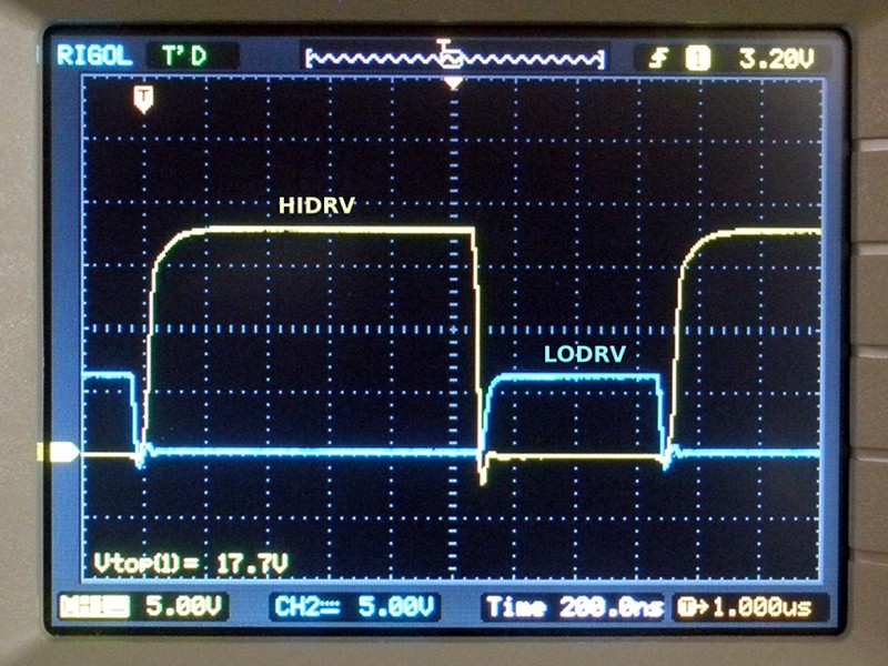
When I power the AC Adapter with a 12V supply and connect a battery simulator, set for 7V with 0.030 ESR the stat lines show charging and REGN measures 6V. The LODRV is low duty cycle and the HIDRV doesn't go above 12V and then settles to the battery voltage. No net current flows into or out of the battery. I wonder if the internal charge pump isn't working properly to generate sufficient HIDRV voltage.
I have the bq24610evm board, customized as described above and it works with the same test setup. I noticed that the EVM board includes a 10-ohm series resistor on BTST which the datasheet doesn't have.
Attached are the HIDRV and LODRV waveforms.
Thanks,
-Ross
Here is an upload of HIDRV and LODRV on my modified bq24610evm board. This is how these signals should look on my custom board.
On the eval board, with a 12V supply voltage, HIDRV goes above 17 volts which turns on the high-side MOSFET fully. However, on my custom board HIDRV only gets to about 12 volts and then goes into a damped sine wave which decays to Vbatt.
Any idea why my HIDRV signal is behaving this way?
-Ross
What is the BSTS pin doing? Is it charging up to 6V when the low side FET is on?
It may be some interaction with the battery simulator. Try a real battery and see what happens.
Hi Charles,
Thank you for your response. We were able to determine the problem last night.
We use a BAT54 Schottky diode which connects between REGN and BTST. The specific BAT54 SMD device we ordered for our PCB assembly had a different pinout compared to the BAT54 device we used in our PCB layout. While these are both three-pin packages, the diode inside the one package is reversed with respect to the other. Flipping the part and resoldering it fixed the problem!
-Ross
Thanks for letting me know.
Glad you found the issue.
Looking at the BSTS pin would have indicated a problem.