


I'm designing a charger for a string of 12 (twelve) car batteries connected in series.
I'm using the bq24450 in Dual Step Current Charger mode.
- The maximum charging current (Imax) of the batteries is 10 Amps. (Battery capacity = 110 AH)
- The input voltage (Vin) is 170 Volts DC maximum. (unfortunately, this value can not be lowered because it comes from a generator)
- The minimum expected Voltage for all batteries in series (assuming each battery is discharged to 10.8 Volts) is 130 Volts (12 Volts x 10.8V = 129.6)
-Then, the maximum voltage through the Power FETs will be 40 Volts.
- In order not exceed the bq24450 supply operating voltage , the ground pin is connected to a tap point in the high side of the tap (second battery in the string, i.e, a maximum approximate Voltage = 27.6 Volts ).
- The pass transistors are two power FET channel-P, p / n: IXTH90P10P.
I put some questions and doubts in the text below.
- Then, I assume that the Voltage Trip will be the voltage sum of the two high side batteries: (13.8V + 13.8V = 27.6 Volts) (used as power supply of the bq24450),
Is it Correct?
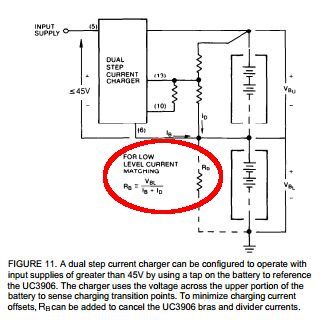
- The figure below (Fig-11 & Fig-10) shows a resistor RB connected in parallel to minimize the charging current offset:
-I'm confused about the calculation of this resistance RB;
- (IB) & (ID) currents: (IB) is bq24450 Operating Current? (approx. 2 mA)?;
- (VBL) voltage: should I consider for calculating, the value of (VBL) when batteries are at 10.8 volts (discharged)? (i.e.: 10.8 V/batt x 10 batt. = 108 Volts)?
- Regarding Reference to Ground (circulated in red color) in Fig-10 (bellow):
- (1) I assume that, with a string of batteries, the ground reference for those points (derived from pins 14 and 15), is the same as pin 6. Is this correct?

Thanks in advance.
Regards.
