This thread has been locked.

If you have a related question, please click the "Ask a related question" button in the top right corner. The newly created question will be automatically linked to this question.

UA78M33 - Incorrect Footprint?

Hi There,

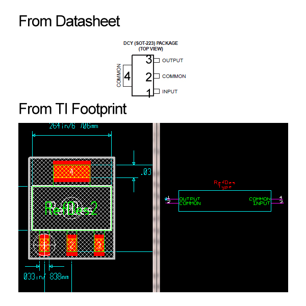
I've recently started using the TI provided footprints for CAD design. It appears that the footprint for the UA78M33 does not match the datasheet (http://www.ti.com/lit/ds/slvs059r/slvs059r.pdf):

For DCY (and pretty much any package) the pin from right to left (top view excluding common tab)is:

  1. Input
  2. Common
  3. Output
However the BXL file for this package assigns the pins as:
  1. Output
  2. Common
  3. Input
Obviously it's a pretty big problem; I made the fatal error of not ensuring the footprint matched the datasheet before manufacture and so have had the regulator giving out ~10V (power supply 12V), and the regulator then frying my 3V3 components and eventually itself. Can you confirm if the footprint is indeed incorrect or am I missing something?
  • Sam,

    For DCY (and pretty much any package) the pin from left to right (top view excluding common tab)is:

    1. Input
    2. Common
    3. Output

    Did you mean left to right?

    Do you have a URL to the location of the BXL file?

  • Hi Ron,

    It looks like all of the UA78M33 footprints are the wrong way round, I don't think its my use of them as the 7805 footprints are fine. I've included an image below to better illustrate the problem. (Sorry for the confusion, I agree left to right should be input, common, output; however on the footprint it is output, common, input)

    Datasheet: http://www.ti.com/litv/pdf/slvs059r

    BXL: http://webench.ti.com/cad/dlbxl.cgi/TI_BXL/UA78M33_DCY_4.bxl

    From: http://www.ti.com/product/ua78m33