This thread has been locked.

If you have a related question, please click the "Ask a related question" button in the top right corner. The newly created question will be automatically linked to this question.

TPS23753EAVM PoE

Other Parts Discussed in Thread: TPS23753, TPS23753A

Hi, 

I have an evaluation board that I did some testing to familiarize myself with the PoE using a external power supply. I was searching for some waveform and it was fine using the external power supply. When I try to pass with the PoE using a PHIHONG PSA16U-480(PoE) adapter, the adapter can't get the class and give me an error. The error code tell me that I have an incorrect capacitive signature.  I change the ferrite bead at the input (FB1 and FB2) cause I broke one of them. They had the same characteristic then the one install for the eval board.

Anyone have a suggestion? The unit is still on Class 0.

Thanks,

Frederic 

  • Please confirm which TPS23753AEVM you have (-001 or -004). Both of these have been tested using SIFOS PDA100 PD analyzer and meet the IEEE POE standard for port capacitance (0.05uF to 0.12uF). Normally, the PSE will not be overly sensitive to this port capacitance and the acceptance range for the PSE is much larger. Maybe there is another problem with the EVM?

    Providing detailed oscope waveforms of the PSE-PD EVM interaction during detect, class, ramp up can provide a lot more useful information.


  • It is not clear if it worked before you replaced the ferrite beads or not.  Adapters/Injectors tend to have a lot of output common-mode (mains) voltage and are sensitive to any instrumentation or other loading on the Ethernet interface.  Make sure you don't have a scope ground or other parasitic loading in the circuit.  Also, you might need to add a little output dc load to maintain the MPS signature.

  • Hi,

    I have the -001 as far as the eval board. I have place/remove a 1.24kΩ load on the 5V output and that didn't change the input. 

    I did not try the PoE prior changing the ferrite beads. I was testing with a DC supply at that point. 

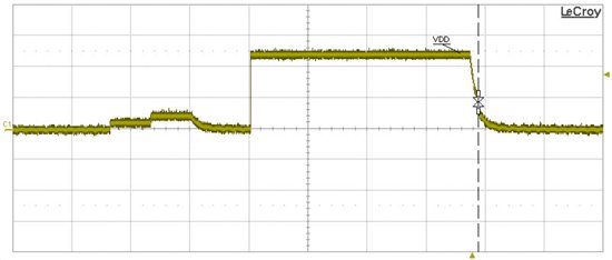
    As far as the waveform, If I compare it with figure 18 from the TPS23753 datasheet page 14 (VDD-VSS), I have the detect portion, the class blend with the last detect  and the unit goes in Turn ON immediately. 

    I don't have any load on the Ethernet side, I place the scope probe right after the bridge when I take a measurement. I was more interested in the VDD signal then the Vout of the PoE adapter. 

    Thanks for your help

    Frederic

  • Everything appears to be working properly, but you do not have the 5V output loaded enough to keep the PSE ON (PSE needs more than 10mA). If you load the 5V output more (say to 100mA) then the PSE should keep power applied.

  • I have place a 47Ω at the 5V out and I still have the same inputs (Vdd-Vss) I have looked at the gate drive to see if that start but it doesn't. It doesn't seem that the hotswap from Vss to RTN get engage. 

  • When you used the DC power supply, did you apply the input voltage between J1 pin 3 and 4 (uses internal hotswap and UVLO) or between pins 1 and 2 (bypasses internal hotswap)? Using pins 1 and 2 will disable the hotswap (using APD pin), but the dc/dc converter will still operate because the input low side is connected to RTN. Using pins 3 and 4 will use the internal hotswap. Try pins 3/4 and note what the input current is when the dc/dc converter is loaded w/47 ohm.

  • Hi Eric, 

    I was actually injecting the power via the Ethernet connector with as per AH2. I was using a ramp up from 0 to 48VDC in 100msec.

    I just give a try with powering the unit on J1 pin 1&2 as you said and with the 47Ω load. I have a input current of 32.124mA so a power of around 1W in @48VDC. 

    Using the pins 3&4, I got an input current of 5.216mA and the unit doesn't power up. The load have no voltage on it, the power on LED is OFF.

    Do I need a ramp up to have the hotswap working? it's not the case with the external power supply on pin 3&4 (since it's almost instant from 0 to 48VDC) neither the PoE adapter as per the screenshot of the scope. 

    Thanks

    Fred

  • Applying Vin between J1 pins 3 and 4 should allow the circuit to work properly and there is no ramp or slew requirement. It seems that the TPS23753A may have been damaged so the internal hotswap is not functional. Without power applied, can you measure (using DMM) resistance between TP4 (VSS) and TP13 (RTN)? Normally, this should be a very high (meg ohms) impedance but if the FET is damged, then the resistance may be much lower (k ohms).

  • Hi Eric, 

    You seem to be right, I have 110kΩ between VSS and RTN (on test points). That seem to be my problem. I wonder what I did to damage the IC.  I will get few new ones and hope that won't happen too often! 

    Thanks for your help!

    Fred