This thread has been locked.

If you have a related question, please click the "Ask a related question" button in the top right corner. The newly created question will be automatically linked to this question.

TLC59116 Brightness Curve

Other Parts Discussed in Thread: TLC59116

Hi,

Good day.

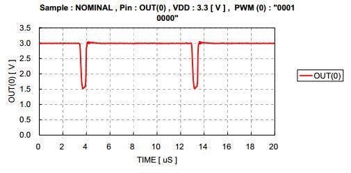
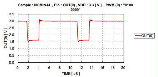
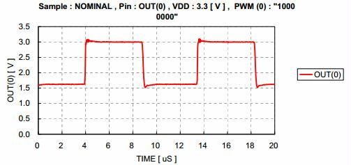
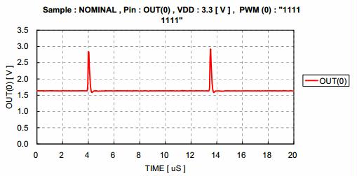
Customer of mine is evaluating TLC59116  LED drive and keen to know its brightness curve. I've attached 2 cases, could you advise which behavior it suppose to be?1881.TLC59116.pdf

Also, could you help to advise the measurement method on how it is done?

Thanks in advance!

  • Hello,

    There are multiple items to consider for LED brightness.  First is the LED itself.  Depending on the specification of the LED, the brightness will change versus the current passed through it.  You also must consider the power dissipation which may change its characteristics.

    The TLC59116 is a constant current device.  When it is programmed via the REXT, the current level is set and will not change with the voltage level.

    On your Case 1 and 2 plots, what is meant by "input for LED driver"?  If that is the LED voltage, the current will be unaffected.  If it is the current, then the brightness is a function of the LED.

    Measurement of LED brightness depends on what you are measuring.  The luminous intensity and wavelength are both important characteristics.  For that information, you need to consult the LED datasheet itself.  

    Regards,

    Dick

  • Hi 

    I understand that LED brightness is also affected by the LED itself, current and etc.

    But, from LED Driver side, we would like to know its own characteristic curve.

    “Input for LED Driver” is referring to Brightness control value for PWM (e.g 0~255) whilst the “Brightness” is the Actual output for Brightness.

    As I browsed through the datasheet pg16, the PWM duty cycle is controlled through 256 step linearly. As such, can I expect the graph is a straight line instead of curve?


    Please share with me if your side have actual data/graph on this so I could share with customer?

    Thanks!

  • Hello,

    Thank you for the clarification.  The PWM0-PWM15 registers set the ON duty cycle when enabled through registers LEDOUT0-3 (14h - 17h).  Since the registers set the duty cycle, this sets the percentage on and off.  When on, the brightness will be set by the LED current.  The brightness will appear to change as the on / off timing ratio changes.  It is not changing the brightness of the LED, only how the eye reacts to the high frequency on / off (with duty cycle set through the PWM0-15 registers). 

    It will appear to be a linear change in brightness.  I have attached some examples of what the output will do based on the PWM register.  The plots show the ON time (output low) based on the PWM register.  The plots show PWM0 register for values of 10h, 40h, 80h and FFh.

    Regards,

    Dick