This thread has been locked.

If you have a related question, please click the "Ask a related question" button in the top right corner. The newly created question will be automatically linked to this question.

TPS7A7001 - Connection Method

Expert 1485 points
Other Parts Discussed in Thread: TPS7A7001

In the datasheet for the TPS7A7001, they show stability curves based on output capacitor ESR and output current.  It looks like an ESR of 0.1 ohm would guarantee stability across the full output current range; however, the ceramics being used would result in an ESR much lower than that.

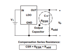
My question is:  What is the proper connection method assuming that there would be a COUT capacitor at the regulator, but also additional bypass capacitors on the voltage rail that the TPS7A7001 is creating?  Should I put a 0.1 ohm resistor in series with the output of the TPS7A7001 and then connect any output capacitors (assuming I can deal with the voltage drop created by the 0.1 ohm resistor)?

  • Rustin,

    The output capacitance referred to includes the bypass caps on the rail. No added series "R" is needed. See http://e2e.ti.com/support/power_management/linear_regulators/w/wiki/tps7a7001-output-capacitor-and-esr.aspx Also, see the attached App. Note.

    snva167.pdf
  • Can you please explain from the Wiki page link below why no series “R” is needed to bring the effective output ESR within the stable range across the entire no-load to full-load range.  At light loads, how is this achieved without the appropriate ESR (especially when including additional bypass capacitance for other ICs on that rail)?  thanks.

  • Rustin,

    My response is based on previous responses from Apps. for this device. I defer to them.......

  • Thanks Jeff.  Can you forward this post to them? 

  • Hello Rustin,

    The issue of using additional bypass caps with LDO's is a tricky one. As you observed stability curves are given for the TPS7A7001 for which  0.1 ohm of ESR will enable stable operation.If you are having trouble finding ceramics with such high ESR values, then you can use the configuration below to add more effective resistance to the ESR of your output cap.

    If your application requires operation with lower load conditions, I would recommend using one of our lower power LDO's which will be stable with lower ESR ceramic caps.If needed, please provide your requirements (Vin, Vout, Iout, Vdo, Package size, Noise etc) and I can suggest parts for you.

    Hope this helps.

    Regards,

    Kartik

  • I was able to change the requirements a bit now to where 0.5A output current is sufficient.  I am now looking at TPS73501 instead.  Is this appropriate?  VIN = 6V, VOUT = 5V, IOUT = 0.5A.

  • Hi Rustin,

    TPS73501 seems ok as long as your peak current is less than 0.5A and you have taken into account the Power Dissipation guidelines. 

    Regards,

    Kartik

  • What creates the peak current limitation of 0.5A?

  • Rustin,

    The TPS73501 has a load current rating of 0.5A. Thus if your application requires transient loads over 0.5A then we need to choose another LDO. If the maximum current draw under all operating conditions is less than 0.5A then this part is ok for you.

    Regards,

    Kartik

  • Yes, I do understand the current rating of 0.5A, I was wondering what causes this limit on the part?  Thanks for any insight on this.


  • Rustin,

    The load current depends on the type, size and layout of the pass transistor used.

  • Ok. Thanks.  So why is the limitation 0.5A when In the datasheet the current limit is shown as 800mA minimum across all conditions?  Why the difference?

  • Hi Rustin,

    500mA is the maximum load current that the LDO can drive while maintaining the specified performance for other guaranteed parameters such as accuracy, drop out etc.

    Under a short condition the LDO can be forced to source more current and to protect the circuitry a current limit, which is built into the design, comes into affect. The current limit can come into affect anywhere in between 800mA - 1720mA of Iout but based on characterization we see a typical value of 1170mA.

    The load current drive capability of 500mA should be kept in mind when designing your system. This is what the LDO can source and if even a higher value due to a transient is required then a higher power LDO should be chosen. 

    This current drive capability is a function of the pass device as I explained previously. The current limiting circuitry is a separate block on the chip which monitors the output and and if the need arises controls the pass device to reduce the drive current. The design of this block determines what the current limit should be.

    Please let me know if you need any more information.

    Regards,

    Kartik

  • Say I need to source a transient up to 750mA or 1A (no idea if this is real as IC datasheets do not typically show transient current draw).  What LDOs would be recommended instead of the TPS73501?

  • All LDO's which can drive up to 1A and meet your other criteria such as Vin, Vout, Iq, Package size, Noise, PSRR etc.

  • Thanks! 

    Do you have any specific recomendations?  Any new LDO from TI with this critera?  Would apprecite a recommendation on a part since you are deeply familiar with the offering.

  • Hi Rustin,

    Can you please provide a detailed description of your application? I will be able to offer better suggestions with the below information:

    • What are you trying to power up?
    • Vin? (I know you already mentioned this, but please confirm again)
    • Vout? (I know you already mentioned this, but please confirm again)
    • Ipeak - I am assuming that this is 1A
    • Is your system sensitive to noise/PSRR?
    • What package size do you need?
    • Is this battery operated? What is your tolerance for supply current consumption for the LDO?
    • Any other features you require shutdown? Capless LDO? Reverse current protection etc
    Thanks
    Regards,
    Kartik
  • Application is running off of a 6V supply and generating 5V for a daughter board.  Contents of the daughter board can vary.


    Vin = 6V

    Vout = 5V

    Ipeak = ??? (not sure of all possible daughterboard configurations and applications as this point…let’s assume up to 1A)

    No specific noise requirements

    SMD package – preferably with good thermal resistance (i.e. MSOP with underside slug or similar?)

    No requirement for particular current consumption

    Require enable pin.  Soft start would be optional.  Need to work with ceramic capacitors.  No reverse protection needed.

  • Hi Rustin,

    For your needs, if you want a fixed output option in order to reduce component count, please take a look at TPS79650.

    If you want a cheaper adjustable option, please take a look at TPS7A8001. This is stable at no load also. 

    Regards,

    Kartik

  • Great!  Thank you.