This thread has been locked.

If you have a related question, please click the "Ask a related question" button in the top right corner. The newly created question will be automatically linked to this question.

BQ24650 - Says it's charging..but it's not....need help please

Other Parts Discussed in Thread: BQ24650

Hey Guys,

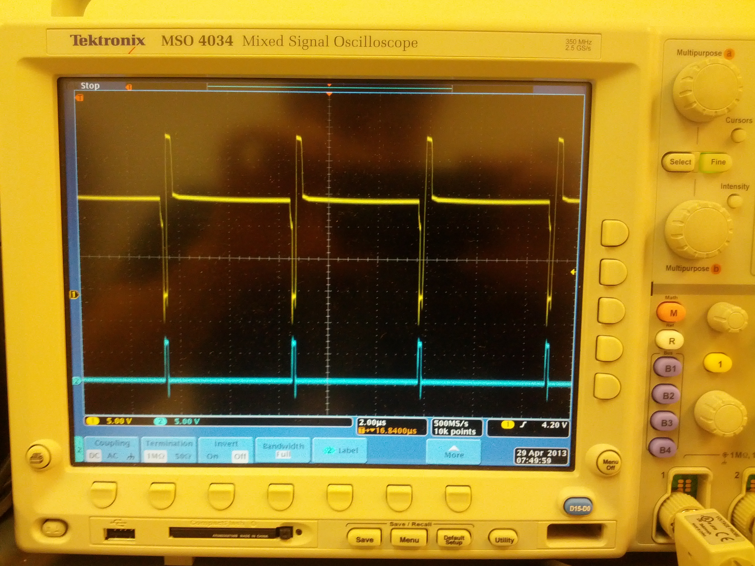
So I just built a test board with the BQ24650, and some other IC's...stuff. I am using a 4-cell LiPO4 battery(6AHr). THough it states I am charging (STAT1 = ON, STAT2 = OFF), it's not charging correctly...if at all. I am getting odd shapes for my waveforms on BTST/PH/DRVH combination of signals. Attached picture is the BEST I can make it look. What is odd is that this picture occurs at Vsolar @ 24V. If I drop Vsolar to say 20V, I get large oscillations on the BTST/PH/DRVH signals. 

Measure the current going into the battery...when Vsolar is 24V, I charge a whopping 50mA..otherwise, the system actually steals ~15mA from me (for <24V for Vsolar). 

I suspect a layout failure, though I have never had one. I did this on a 2-layer cheapo layout. The ONLY think I can see that is bad, is that I have the PH going right under the boost diode(which is not good). 

Vfb and MPPset are super clean looking....

I have a separate ground place for the switchers, power caps(15uF), flter caps(15uF).

Please take a look at the picture and let me know if this is expected. As a remind...this is the BEST  Ican get it...when I cool down Vsolar to 20 or less, I have huge ringing during high/low transitions =/ does the boost dioe do this? that's my guess...

Thanks,

-Peter

  • Is your schematic identical to the basic application schematic with the same input caps and output LC?

    Does your board work with a lab supply as an input?

    I would compare your board to the operation with an EVM.  If the EVM works, I would guess it is an issue with your board.

    Take photos of each pin of the IC...best to compare them to the EVM.

    Make sure your TS pin voltage is within range.


  • Can you please comment on the picture I provided? This is a pic of DRVH and DRVL. Looks like I have a very violent transient on DRVH...not sure where it is coming from.

    To answer your questions:

    1) Schematics Identical except I added some series termination resistors(20 ohms) for DRVH, DRVL, switch those to jumpers...transients got worse.

    2) How much noise is generated from the boot strap diode? I may have placed it too close to PH/DRVH, DRVL, and could ring on those lines..causing some injected feedback noise.

    3) I do not have an EVM...perhaps I should buy one =/

    Thanks,

    -Peter

    Thanks

  • Assume the top signal is the switch node and the bottom signal is the low side drive?

    Can't get much information from this.

    Can you lift the inductor and connect with a loop and get ainductor current waveform?

    Still would try and compare this with an EVM.