Dear TI community,
I've got a problem with the TI LM25088-2.
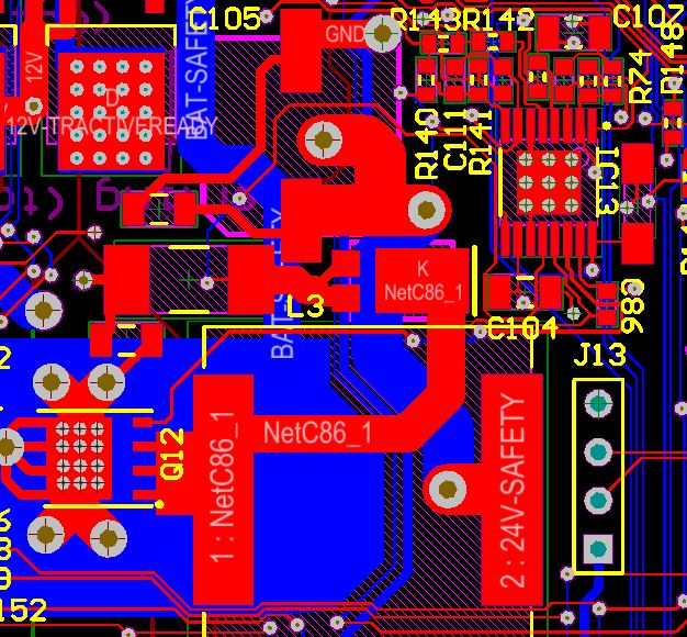
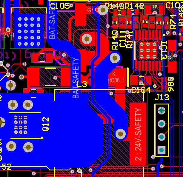
My schematics:
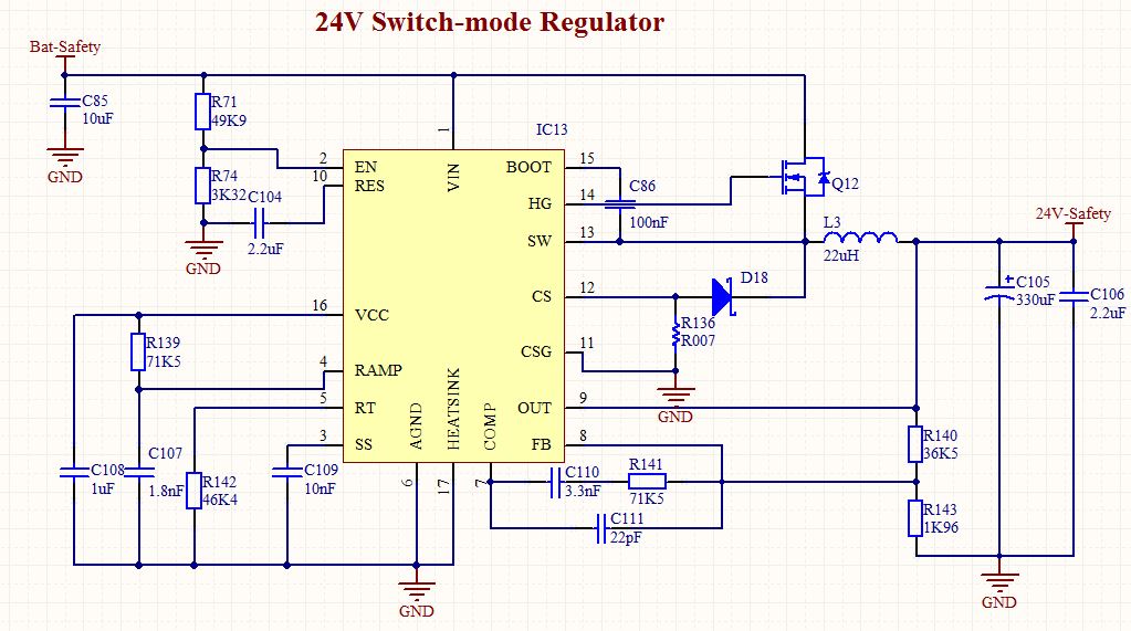
I've designed this using the WeBench designtool. It is designed for converting 35-26V to 24V. It should be able to supply about 8A of current. The MOSFET is the IRFH5006TR2PBF, the diode DIODES PDS560-13, the inductor VISHAY IHLP6767GZER220M01 and the 330uF cap is the Panasonic EEEFK1V331AP.
When I put a voltage bigger than 19V on the Bat-Safety, the enable pin of the LM25088 rises above 1.2V, and the converter switches on. But once it's switched on, the lab power supply (limited to several different current levels, the highest I tried was 2 (!) A), switches to current protection and back to normal operation, and so on. This repeats several times per second. The waveform measured on the output of the converter is a sort of sawtooth, where the rising part is just a very short time and the rest of the time is falling. A bigger current limit doesn't really change this behavior, and also a bigger voltage (up to 35V) didn't change it.
I measured the gate voltage. The gate voltage showed some strange behavior: it didn't seem to rise higher than the output voltage. The strangest thing was: it did show some sort of periodic behavior of about 150kHz (about the frequency set), but between the high 150kHz pulses there were 6 other pulses. Also, the pulses weren't formed like a square wave, but like a damped sine.
The strange thing is: somehow the current from the powersupply goes to somewhere, but I don't know where. I also measured the voltage on the measuring resistor (R007), but this didn't seem to rise any time (so the inductor current is about 0).
I've also tried to put 24V on the output of the converter, and at the same time 24V on the input of the converter. This showed that there's no problem with the circuit after the converter (which by the way consists only of closed switches, so should not use any power), because the current limiting of the power supply didn't occur now. In fact, the converter seemed much more stable.
One last thing: the pcb was made twice, and on both pcb's the behavior occurred, so it probably is some design error.
I hope that any of you can point me in a direction to look for errors. I'm out of ideas, and I can't explain the strange behavior...
Thanks alot!
Vincent Grijze