This thread has been locked.

If you have a related question, please click the "Ask a related question" button in the top right corner. The newly created question will be automatically linked to this question.

CSD18532Q5B Rise & Fall Time

Other Parts Discussed in Thread: CSD18532Q5B

What is the best method to approximate the rise and fall time of CSD18532Q5B with Vgs=5V (or 4.5V is this is readily available)?

Datasheet provides these values for Vgs=10V, Vds=30V, Ids=25A. not for Vgs=5V (or 4.5V). Ideally I would like an approximate formula to compute these values to include in an analytic model of the converter however a fixed value would suffice for initial calculations.

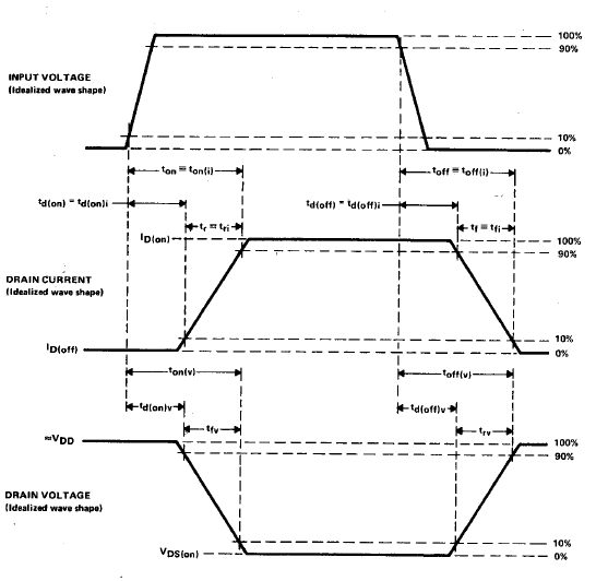
Similarly if Td(on) and Td(off) are impacted for Vgs=5V (or 4.5V) compared to datasheet values at Vgs=10V please provide approximate values.  

  • Niyant, 

    Before I tell you something incorrect, I want to check with the expert who writes our spice models. He is out on leave but should be back Monday. I will try to get you some feedback then. 

  • Niyant, 

    Unfortunately, there is no straightforward means of calculating modified times based on the values provided in the datasheet. Therefore, I would encourage you to use our P-Spice model, which is available on the web (http://www.ti.com/product/csd18532q5b#simulationmodels) in order to procure the values you need. 

    Just a word of caution. To compare any values with those measured and on the datasheet, make sure you are using the JEDEC standard definitions, provided here. 

  • Brett,

    I was able to collect some Ton, Toff, Rise and fall time estimates using the SPICE model. I notice for VGS=10V, VDS=30V, IDS=25A the Toff delay ~ 21.9ns while for VGS=5V, VDS=30V, IDS=25A the Toff delay ~9.5ns.

    This is a major difference between Toff delay between the two gate drive voltages can you shed some light as to the primary MOSFET characteristics driving this difference? For my application Toff delay is very critical (sync rectification) so any information you can share here will help me understand the changes better. 

    Tf and Tr were slightly different between the two gate drive voltages but not by much. There is ~12% increase in Ton delay as well. 

    Thanks,

    Niyant

  • Niyant, 

    Your results make sense with what  we would think.

    I would not expect a great discrepancy between tr and tf because you have two factors that basically cancel each other out. On the one hand, driving the voltage at 5V, the rise time is depended on charging the gate to Qg(5V) = 27nC as opposed to Qg(10V)=52nC. However, because your voltage has halved but your gate resistance has stayed the same, your current is going to be about half. Thus you are building up roughly half the charge with roughly half the current. The same argument could be made for discharge. 

    On and off delay times are a function of the threshold voltage (and therefore threshold charge). When charging up, it takes roughly the same amount of time to hit this limit and induce device turn on. An increase in on delay time can be explained by the decrease in gate drive current due again, to the halving of Vgs. However, when at 5V, because you are much closer to the device threshold, it will take much less time for device to hit threshold on the way back down, which explains the dramatic decrease in turn off delay time from 10Vgs to 5Vgs.