This thread has been locked.

If you have a related question, please click the "Ask a related question" button in the top right corner. The newly created question will be automatically linked to this question.

LMZ14203H dynamic output adjust

Other Parts Discussed in Thread: LMZ14203H, LM10010, LMZ14203

Hi all,

I want to use the LMZ14203H to set variable output voltage. For this reason I cannot use a fixed resistor vaules on the feedback input of the LMZ14203H. In want to use a dynamic configuration that can set the output voltage depending on an analog voltage that we can call vset. Looking to the datasheet I see that the LMZ adjust its output by means of a comparison between the voltage on the feedback point and a fixed 0.8V.

Now, I connected the feedback pin to the output of a circuit that gives:

Vo + 0.8 - Vset

where Vo is the LMZ output. This way, the LMZ works in order to have its output equal to Vset, thus having 0.8V to its feedback pin.

The circuit seems to work quite well, but its behaviour strongly depends on the value of the capacitance that I use in the LMZ output.

Is there an application note or some configuration to use a feedback pin as a vset adjusting pin?

Can anyone help me in this topic?

Thanks.

  • Hi Polp,

    There are a couple of options for adjusting the output voltage.

    1) You could use a VID controller such as the LM10010. 

    2) You can add a second resistor to the FB node to subtract Vset from the output voltage.  Method Determine Top and Bottom resistorrs for nominal Vout + 0.8V.  Add a second top resistor but connect it to Vset instead of Vout.  When Vset is low the output voltage will be will be at its highest value.  When Vset is high the output voltage will be drop. You can adjust the gain with the resistor choice

    2620.Programmable_Power_Supply.pdf

    I attached an article describing the process.  Watch out, I remember the publisher added a typo on one of the equations but can't remember which one. 

    As for the stability concern.  You might need to add  a capacitor to filter your Vset before it reaches this circuit to roll off any noise.

    Also, when you design the output capacitors you need to pick caps that are rated for the highest voltage you are seeing, but have enough capacitance for the lowest voltage.


    Regard,

    Marc


  • Hi Marc,

    thanks for your help... It works correctly!!

    Another question... I tried to use the LMZ14203H for output voltage even lower than 5V and it seems to work correctly...

    Which is the real minimum output voltage limit that I can reach? Is it only a efficency problem?

    Thnaks again...

    Best regards,

  • Glad to hear that it is working for you.


    I response to the lowest ouput voltage.  Because you are using an adjustment cicuit you can make the part go to very low voltages.  However, the part won't have been tested for stability at these lower output voltages so it will be up to you to determine if entire system is stable.


    Regards,

    Marc


  • Hi Marc,

    I'm here again.
    I am currently using the LMZ14203H with the output adjustment voltage circuit you suggested me.
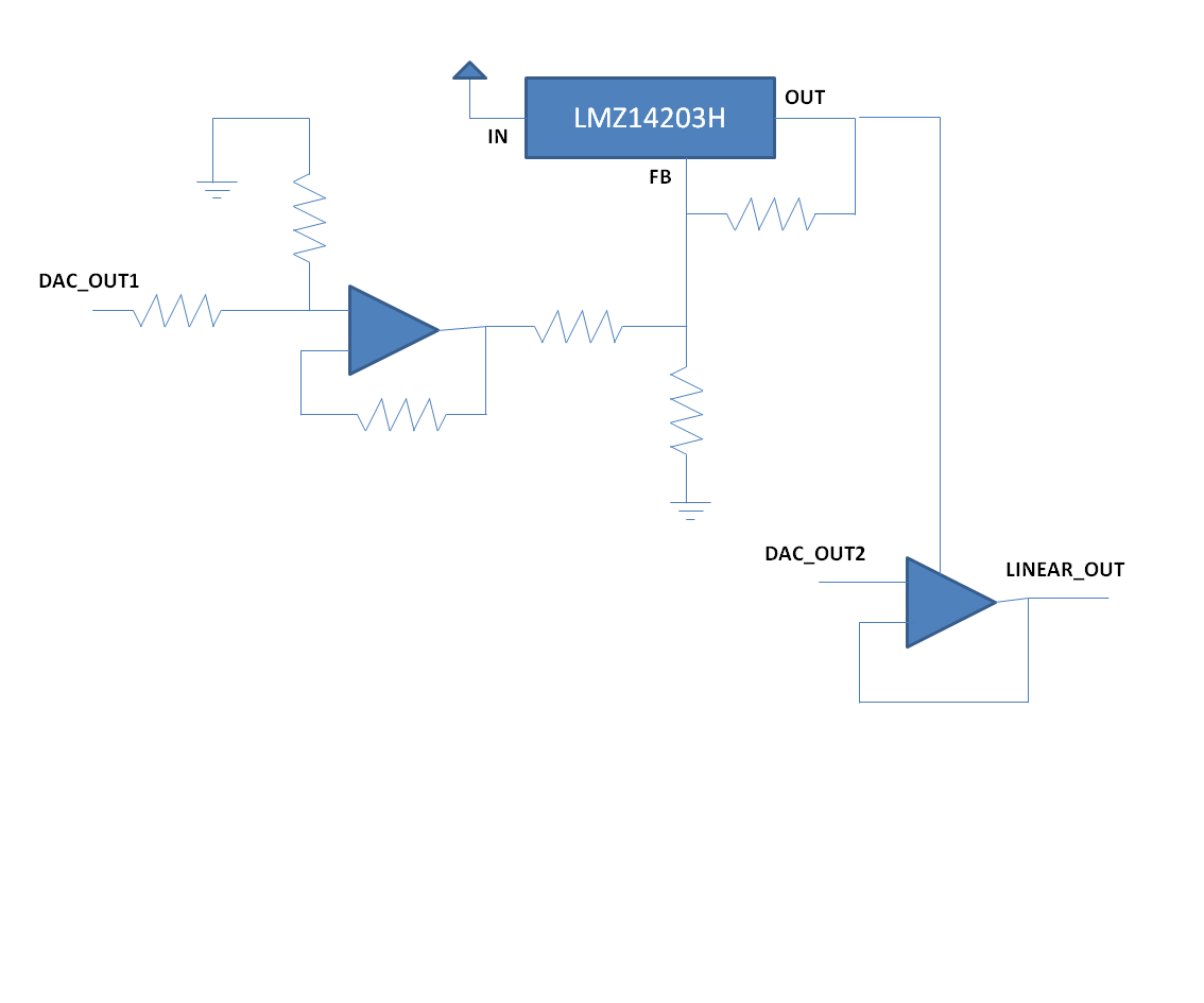
    The LMZ output is directly connected to the rail of a linear power amplifier. I want to adjust the rail in order to minimize the power consumption on the linear amplifier... thus I am adjusting the LMZ output depending on the amplifier input voltage (just setting the LMZ output to 1.5-2V over the linear amplifier).
    To this end, I noted that, even if I force the LMZ to be at 5V with the adjustment circuit, when I set the linear amplifier to 10V (just an example), the LMZ sets automatically its output to 11.5V that is the minimum voltage that allows the linear amplifier to work correctly.
    Is it a correct behaviour?
    Can I avoid to adjust the LMZ output just setting the linear amplifier expecting to have the LMZ setting its voltage to 1.5V over the linear amplifier?

    Thanks for your support.

    Regards,

    Polp

  • In attach you can find a simplified schematic of the circuit I am referring to.

    Specifcally, we have that:

    1 - (normal mode)

    DAC_OUT1 = 5V   --> LMZ_OUT = 12V

    DAC_OUT2 = 10V --> LINEAR_OUT = 10V

    or for example

    DAC_OUT1 = 0V   --> LMZ_OUT = 5V

    DAC_OUT2 = 3V --> LINEAR_OUT = 3V


    2 - (under investigation)

    DAC_OUT1 = 0V --> LMZ_OUT (expected) = 5V

    DAC_OUT2 = 10V --> LMZ_OUT = 11.5V ; LINEAR_OUT = 10V

    Is the 2- behaviour  correct?

    Can I normally use it?

  • Not sure what is happening, let me think about it.  Maybe a parasitic in the op-amp is turning on.

    Can you give me a plot of the output of the LMZ14203 vs DAC1 Voltage from 0 to 5 with DAC2 set to 3.3?

    Then do the same plot with Dac2 set to 10V.


    Regards,

    Marc