This thread has been locked.

If you have a related question, please click the "Ask a related question" button in the top right corner. The newly created question will be automatically linked to this question.

TPS63000 Start-up Issue

Other Parts Discussed in Thread: TPS63000, TMS320C6746, TPS62080

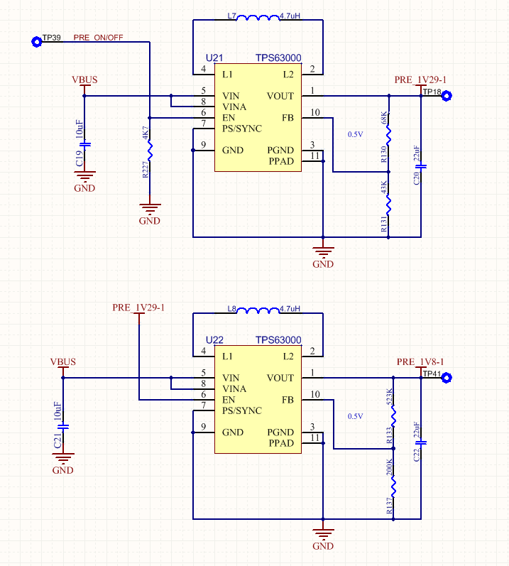
We are using two TPS63000 devices to generate two of the supply rails for a C6000 DSP (TMS320C6746). Due to the power-up sequence requirements of the DSP, the voltage rails are cascaded with the 1.29V supply driving the enable line of the 1.8V supply. Even though the minimum "ON" threshold for the enable pin on the TPS63000 is stated as 1.2V, we have found that our 1.29V enable signal is still not high enough to consistently switch on the TPS63000 (some times it does, some times it doesn't).

This problem seems to be limited to our latest production batch only and I was wondering whether there had been any similar complaints received for a specific revision of the silicon, or perhaps a specific production batch of TPS63000 devices?

For reference, our schematic is shown below:

  • Your configuration should be working so I would look at the various voltages with a scope to see what's going on.

    Your inductor is very large and output cap very small, compared to most applications.  This may lead to instability.  I recommend reducing your inductance.

  • Hi Chris

    Thank you for your fast reply. Luckily I had a 2.2uH inductor on hand and could test your theory. The PSU now consistently starts up and is stable with the 2.2uH inductor in place. Thanks!

    As you can see from our schematic, we have the Power Save mode enabled (PS pin pulled LOW). Might this (in combination with a very light load) have contributed to our issues with the PSU's start-up?

    Regards

  • I would expect that you could see stability issues in either power save mode or PWM mode with such a large L, small C combination.  

  • Hi Chris

    I revisited our calculations, following the TPS63000 datasheet recommendations for minimum inductor and minimum output capacitor selection.

    Assuming a max input supply voltage of 5.5V, I calculate a minimum recommended L of 2.6uH for the 1.29V supply and 3.3uH for the 1.8V supply. In order to keep our BOM as small as possible, we want to use the same L and Cout for both PSUs, so I chose the 3.3uH inductor for both. However, seeing that the family of chip inductors that I was looking at have a tolerance of 30%, I concluded that I will have to take an even larger value inductor just to be safe and ended up selecting a 4.7uH inductor (i.e., 70% of 4.7uH = 3.3uH).

    The datasheet recommends that the minimum Cout = 5 x L, which works out to be 23.5uF for a 4.7uH inductor. So our 22uF (+/-20%) capacitor was definitely on the low side.

    It follows that for our application the inductor needs to remain 4.7uH, though the output capacitor will have to be increased substantially. The datasheet however also states that the recommended inductor value range is between 1.5uH and 4.7uH, thus placing us at the upper limit of the recommended range. Indeed, seeing that we have a 30% tolerance on our inductor, we may very well end up with an inductor on the board that has an inductance of 6.1uH -- clearly outside the recommended range.

    Seeing how sensitive the switcher's stability is with regards to L and Cout, I'm afraid that we may run into problems in production if we use the 4.7uH (+/-30%) inductor and a 33uF or 47uF or larger (+/-20%) output capacitor.

    What would your recommendation be in this instance?

    Many thanks

  • The inductor sizing equations are just recommendations.  It is more important to stay within the recommended range.  

    I would advise having much more output capacitance.  Though dc bias concerns at your low Vouts are minimal, you will lose some capacitance from that.

    But I guess I'm curious why you are using a buck-boost converter when a buck converter would do just fine for your Vin and Vout ranges?  You might look at the TPS62080 instead.  It would be much simpler.

  • In other words, a 4.7uH inductor with a 30% tolerance (i.e., 6.1uH worst case) would be too high? Would you rather recommend a 3.3uH, given the choice?

    I am adding more capacitance. Unfortunately the footprint on our board is 0805 and the highest available X5R capacitor is 47uF.

    The reason for using this specific buck-boost converter is simply because we are already using it in a number of other places in our design where buck-boost is required (our bus voltage can vary from 5.5V down to 2.7V) and we are trying to keep the BOM as small as possible.

  • Ah, I think I see the question now.  The datasheet values for the inductor are nominal values, so we know there will be some tolerance with that.

    You can use 4.7uH, but you always need to test your circuit to make sure it works for your application.