This thread has been locked.

If you have a related question, please click the "Ask a related question" button in the top right corner. The newly created question will be automatically linked to this question.

LM3478 - Boost

Other Parts Discussed in Thread: LM3478, LM3429, LM3481, LM3488

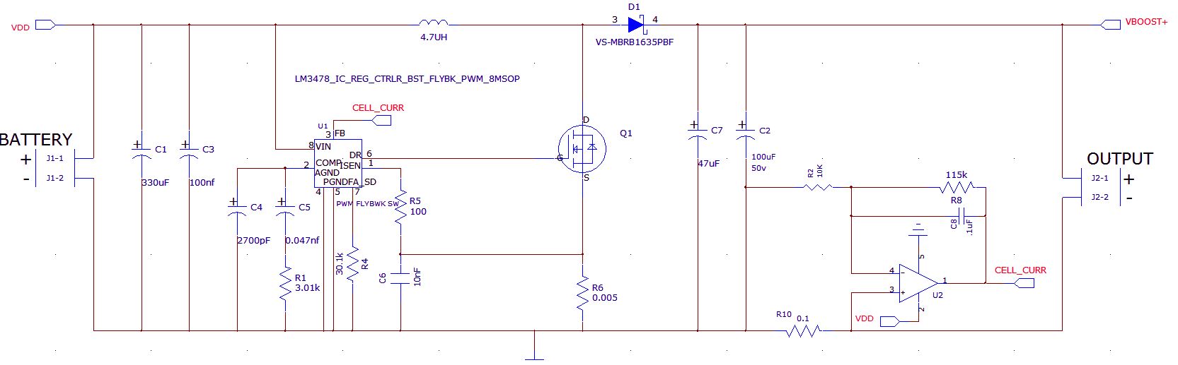
Hi all, I would like to use a LM3478 as a constant current supply at 1.0 amps 9 to 18 vdc. I have two ways i would like to do this one is by using a digipot in the voltage divider circuit that feeds the 1.26 volts to the FB pin. The other way I was thinking about is, can I send an output from an analog output pin on a pic to the FB pin directly, of course I would have a shunt and current measuring op-amp that would tell me when my load has reached 1.0 amps. Put another way, can I input a lower voltage then1.26 to the FB pin to increase Vout, then inject 1.26v when the I have satisfied the current requirement?  Would that work, why or why not?

-Bill

  • Hi Bill,

    Are you stuck on using the LM3478 for this application or would you consider using an LED driver (like the LM3429) that is meant to regulate current instead of voltage?

    Best regards,
    Tommy 

  • Tommy, 

    I'm not stuck, but I would like to have an IC that can run as low as 3.3V for Vin and does the LM3429 max out at 1.0Amps. That I could live with the Vin of 3.3v is a pretty hard requirement though.Anything like this that can run down to 3.3v ?

    -Bill

  • Hello Bill,

    You might take a look at Thread ID: 267530 for a similar application discussion and some concerns.

    Also, please elaborate on the application power parameters if you can. Is the input power source a regulated 3.3V source? Or is it desirable to have a wider input  range?

    Am I correct in understanding that you want 1.0A output current with a required compliance voltage range of 9V to 18V.  Do you need adjustment capability of the 1.0A current level, or is it always 1.0A.  How much accuracy does the 1.0A current need to have? Is the load a string of LEDs or something else?


    Alan Martin

  • I will look at the thread! I have a battery operated device and would like to run from 4 AA rechargeable batteries. The device only needs to run 20 - 25 minutes before recharging. So the source is not regulated. The input range would be from 3.6 to 5.6 volts. The output is correct 9 to 18vdc @ 1.0 amps. This is not an LED device it's an electrolytic device, it is a constant current device. I need to be to -/+5% from 1.0 if Thanks for the help !

  • Hello Bill,

    Thanks for the clarifications.  Attached is a scan of a hand-drawn schematic concept based on the LM3481. The LM3481 is a later incarnation of the LM3478 and is much better suited.

    In this application I have implemented current sense on the low side of the load. Is this permitted?

    I now realize that the resistor values for the output over voltage clamp divider string will need to be adjusted.

    3250.20130530160534610.pdf

    Note that this does not include and ON-OFF mechanism to disconnect the battery source from the supply input. Also note that the resistive divider for the output over-voltage clamp remains attached across the load when the supply is in shutdown.  There is a work-around if this is an undesirable discharge path once the load is charged and the supply is turned off.

    Additionally the input UVLO divider remains connected across the battery and will eventually deep discharge the battery unless we add some sort of on-off battery disconnect.

    This schematic is a starting point to get the discussion rolling, not the final solution yet.

    After the electrolytic load is "charged"; does it get disconnected from the supply? In other words, is there an output disconnect connector?

    Alan Martin


  • Alan, 

    The current sense on the low side is permitted, and an elegant way to make a constant current supply at 1.0 amps. I have a couple of questions one, about the current sense resistors, because this is a battery operated device I don't want to spend the battery energy on the drop across the 1.25, 2 watt resistor. Is there a work around, my best is to take an op-amp and some and a very small valve resistor and set the gain such that the 1.275 volts will be created when the shunt sees 1,0 amps through it.

    Second, what is the best way to shut this chip down, I will be running a Pic processor, should I just use an open collector to power it up and then set the transistor base high from the pic output to shut the LM3481 off ?

    thx

    -Bill

  • Hello Bill,


    Thanks for allowing me to refine the circuit. The added components implement the best way to get zero power shutdown.  Hope it isn't too many parts.

    Alan Martin

    5810.20130605174758543.pdf

  • Alan,

    That's looks great, just what I was talking about. You are big help.

    You might not be the right person or company for this question but here goes.

    I have another question and this is on the input side. I have done some experiments and (4) batteries are heavily loaded around 5 Amps when delivering 1.0 amp @ 12 v to the load. 12v  is the nominal voltage.  The requirements for the battery pack are  must cost < $3.25 in high volume , rechargeable,  must last 11 minutes before recharging. Must be able to deliver the high current so the boost circuit can do it's job.

    thx

    -Bill

  • Hello again Bill;

    This is actually a fun question to try and answer.  First some simplified math. Your load is 12V x 1A = 12 Watts.  Because of the efficiency loss in the boost the approximate input power is around 15 Watts. Your requirement is to deliver 15W in 11 minutes.  Multiply 15W x 11minutes x 1 hr / 60 minutes and you get 2.75 W-Hr energy requirement.

    The next thing is to double or triple this number so the battery isn't ruined by deep discharge. Let's just double for now. So let's say a 5.5 Watt -hour battery pack is what you are looking for.  Based on minimum cost requirement for a rechargeable battery as well as needing a very high allowed discharge current I would recommend a sealed lead acid chemistry over NiMH, NiCAD, or Lithium "x" types. The trade-off is larger size and weight.  But SLA will win because of the cost and high current demands.

    Batteries are specified with Amp-hour ratings, not Watt-hour.  So take 5.5 W-hour and divide by 5.5V giving  1 Amp- hour 6V battery requirement.

    Next you need to be aware that the amp-hour capacities of batteries are based on 10 or 20 hour constant current discharge rates. If you try to pull 1/2 the internal energy out of the pack in 11 minutes you find you have to spec a much larger Amp-hour product. (If you are lucky, the battery manufacturer will also have graphs of constant power discharge rates in addition to constant current.)

    Let's look at a common 6V SLA available through the leading Internet / mail order distributor of parts.  They have 6V 3AH assembies that are 5.28 L x 1.34 W x 2.60 " tall that are in the $10 range in volumes of 1000.  (Not sure how much this declines in high volumes and this distributor has notable markup. )  I think this assembly would be an appropriate choice for long service life in a product. But I don't know what usage profiles you need. Amp-hour ratings less than 3AH might work but will have higher losses and shorter service life.

    One good thing about SLA assemblies is that they have power tab stake type terminals instead of the button type terminals of common AA, C or D cells. So your product doesn't experience the cost of a battery tray and socket and you will have low loss connections with crimp-on terminals and a heavy gauge wiring harness to your board.

    Other thoughts:

    If you "fast charge" any type of rechargable battery you have to use a charger that has enough intelligence to know when to stop; other wise the battery gets damaged and / or there is a resulting safety hazard.  Most "non-fast" chargers take around 16 hours to restore a battery to full charge. Slow chargers are cheaper and smaller of course.

    Whatever battery chemistry you end up with in the product consider the following:

    The circuit I gave you does not have an input polarity guard: If the battery is attached with reverse polarity, all active circuitry will be damaged. The simplest polarity guard is a series input diode, but this has the drawback of wasting a lot power when you pull ~5A through it for 11 minutes. The second method is a series P-channel MOSFET in the positive lead of the circuitry input. This would need to be a high current low RDSon P-channel fet that doesn't waste too much power at 5A.  This may be too costly. A lower cost alternative is to place an N-channel equivalent blocking circuit in the ground lead of the battery feed to the supply. But I normally don't recommend that the "ground end" of the battery not be tied directly to ground.  But N-channel MOSFETs will be much cheaper than the P-channel counterparts. So it may be an option if your system allows.  The final scheme is to use a reverse-biased high current silicon diode across the input terminals of the supply and a series fuse that blows out if the battery is attached backwards. I don't like this scheme myself because the diode is huge and has an associated leakage current that always drains the battery. But you should consider one of the four options to prevent manufacturing mishaps from creating scrapped assemblies. Pick one method and we can possibly adjust the schematic.

    I don't understand the mechanics of the end product or the nature of the 9V to 18V electrolytc load but you need to also be aware that boost converter don't have shorted load current limit at all. If you attach a shorted electrolytic load, battery current flows "without bound" into the shorted load even if the boost supply is disabled. The CVCC circuit provided only has voltage compliance down to the input battery voltage.  If you pull the output voltage below VIN, output current then escalates.  If you want a safer topology with compliance down to zero volts then a transformer based SEPIC would be a better choice. Very similar schematic to what has been presented already. (A SEPIC is just a 1:1 flyback with a superiority complex ;). (My joke)  I think you should consider this because of the very high currents you can get from the battery pack. High fault currents can cause damage to circuitry and present injury and liability hazards.

    The bottom line is that the battery cost target will be challenge. On top of that, all of my other recommendations to improve safety and yield of the product are all cost adders.

    Sorry if I'm long winded about this. But I've designed portable medical devices that sold in high volume and these experienced many of the problems I'm cautioning you about.

    Alan Martin


  • Alan,

    Thanks I found the battery you were referring, your right heavy and still around the price range that were are spending now. I've been through this exercise in my cube and in the lab, your pretty much spot on with your suggestions. This is all great information thanks again for your help.

    -Bill

  • Boost circuit using a LM3488. I have set this circuit up on the bench, it's a 1.0 amp constant current supply. I am getting some unexpected results, the FB pin from the op-amp circuit should be around 1.275v when the current is 1.0 amps through the load.  Instead, the load current reaches 1.7 amps and the FB signal is about 1.46v  . My op-amp and shunt circuit is working fine, shouldn't the output voltage stop climbing when the FB reaches 1.275v? What advantage does the LM3481 have over this chip in my application?

    -Bill