This thread has been locked.

If you have a related question, please click the "Ask a related question" button in the top right corner. The newly created question will be automatically linked to this question.

TPS63700 does not always come up

Other Parts Discussed in Thread: OPA2277, TPS63700

I also got some rely annoying start up problems with the TPS63700D.

I was follow the typical "Figure 15. Circuit for –12 Volt Output" from the datasheet page 13 application solution to make +/-12V supply for some Operation amplifiers

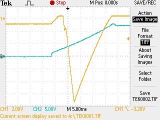
The thing is that +12V produced and start first to then supply +5V power and then the +5V supply the TPS63700D. So the supply to the TPS63700D start ~2.5ms after +12V and during that time I see that the -12V rail rise up to approximatly about +0.3V. Then the -12V ramp down to approx peek to 13.5V and direct after that the -12V rail turn off and fall back to +0.3V and will never turn on. If I manualy remove the +12V supply to all the Operation amplifier then there is no +0.3V on the -12V rail before startup and then the start up problem never occur. But this start up constraints is realy annoying because there is common to produce +/-12V supply to OP circuits (several OPA2277). Pleas answer if you have some solution for this. olle@dst.se

  • I split this thread since yours is a separate design from the original post.

    I don't quite follow your description, so perhaps a waveform would better convey what you describe.  In any case, I would recommend testing with the EVM as the layout can affect the device's operation.

    Another option for you is a split rail supply, as shown here: http://www.ti.com/lit/ug/slvu374/slvu374.pdf

  • I was fix this problem by monitoring the -12V rail with my FPGA controller and if -12V not start up then I  PULL DOWN then ENABLE signal a short while by my FPGA controller and then I got 100% restarting of this TPS63700.

  • Here is the waveform:

    Yellow line is the -12V rail how not startup proper when there is a load of 8numbers of  OPA2777 operation apmlifare how get the +12V  power rail BLUE LINE  how also

    supply the +5V regulator how then will supply  the TPS63700D. My solution was to monitor this -12V rail and if not start up proper like this waveform then I was PULL DOWN the ENABLE signal a short while then it always start up after a reset.

  • Yes, your solution is a good one.

    You also might look into the ~ -1V pre-bias on the output voltage as well as your board layout.  This device, like all switching power supplies, is sensitive to the board layout.  You should copy the EVM for best performance.

  • What is "pre-bias" on the output voltage regading this. (I know that switching device like this should have a tight routing on PCB to prevent EMC/EMI ringing problem with stray inuctance to the switch diode and so on, is "pre-bias" level some sort of a result of PCB stray incutance and capacitance ?)

  • A pre-bias is when some voltage does not start from 0V.  Your output voltage shows this.  It is typically the result of some leakage paths onto the output--from the positive rail of your op amp for example.

  • Thanks then I know what you mean with the pre-bias and of course that's te result of the backwards current when +12V supply to the 8 OP2277 circuits at start up. I was a bit concern about this "backwads current" thorue -12V rail during start up so I was test to add on a low voltage schottky power diode to hold down the pri-bias voltage but it not change the behaviour of the start up of the TPS63700D, the DC level of the pre-bias was shift down some voltage when I have add the external schottky but the delta shape of the voltage look almost the same,  it's look's more like the start up behavoiur/shape (regardless DC level) of pre-bias delta voltage affect if the  TPS63700D will start or not not more then depend on the the DC level of the pre-bias.