This thread has been locked.

If you have a related question, please click the "Ask a related question" button in the top right corner. The newly created question will be automatically linked to this question.

TPS61025 low impedence path to ground failure

Other Parts Discussed in Thread: TPS61025, TPS61052, TPS61070, TPS61200, TPS61260

Hello,

I have a customer that is seeing a failure on the TPS61025 after various shock and vibe testing.

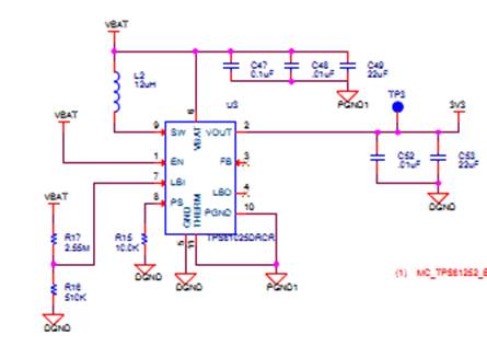
They are seeing a low impedence path to ground through the SW pin.  On the order of 30ohms measured by removal of the part from the board and measuring the resistance through the SW pin.  This is causing roughly 200mA to be pulled and therefore draining the battery very quickly.  During normal operation they see an output load current of <1mA during standby and about 70mA during power on mode.  They have the circuit for this device set up as you can see below in the image:

Can you please advise on next steps we can take to understand the root cause of this issue?


  • It looks like the device they are using is the TPS61025, not the TPS61052?

    As you may know, most failures with boost converters are layout related.  They need to have a good layout, especially with this device.  

    In addition, they need to use the proper output capacitor configuration noted in the datahseet.  This device needs ESR in the output cap and does not support ceramic caps.

    I would recommend using a newer device, such as the TPS61200, if their power specs allow it.  If they need only 70 mA output current, then either the TPS61260 or TPS61070 are much preferred, being lower current, smaller solutions.

  • Hi Chris,

    Thank you for the input! I had a call with the customer today and it looks like we might move to the TPS61200.

    For the record, the information I received back from him is that he believes the layout seems find except that the 22uF output cap is a ceramic one and also placed very far away from the converter.  Obviously this is not a positive in this design, but do you believe this could be the cause of a low impedence path to GND to present itself on the SW pin?

    They are doing a board spin so I want to be sure to catch any issues that may be present and could affect the TPS61200 should it replace the TPS61025 device currently there

  • Yes, 'output cap very far...' will cause a boost converter to fail.  This is true for any boost but especially the older TPS6102x family.

    We recommend copying the EVM layout for any switching power supply design.