This thread has been locked.

If you have a related question, please click the "Ask a related question" button in the top right corner. The newly created question will be automatically linked to this question.

TLV70236- unable to get an output

Other Parts Discussed in Thread: BQ24072

Hello,

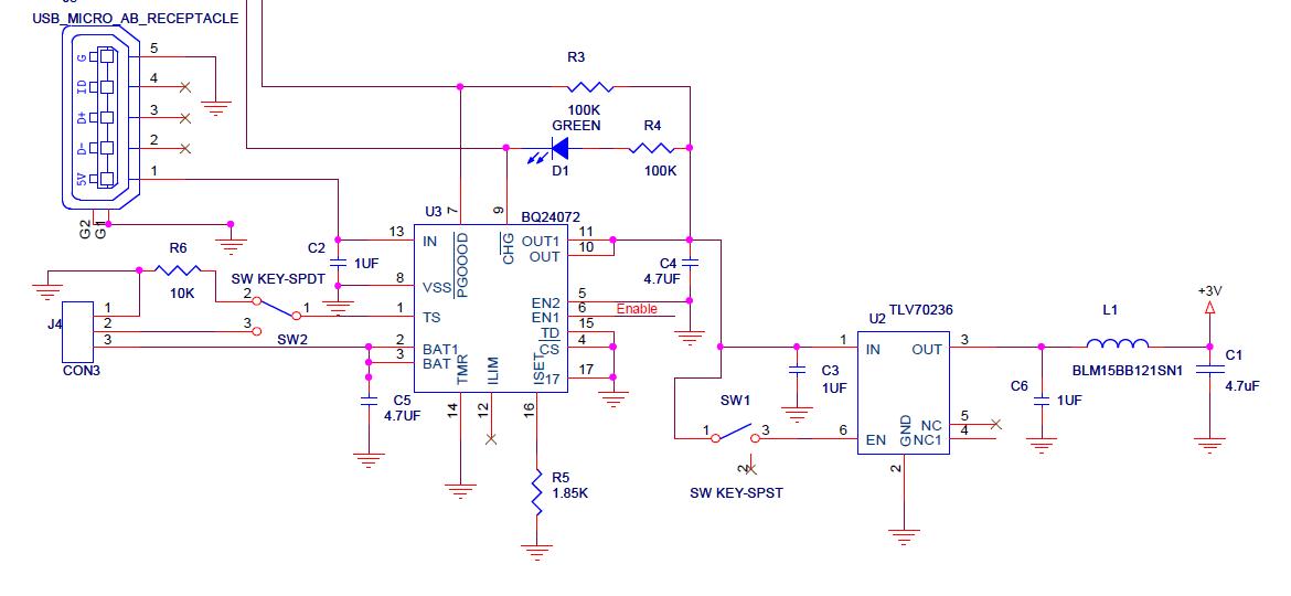
We are using the TLV70236 LDO which gets its Vin and Enable from TI's BQ24072 charge management IC as shown in the attachment. The TLV70236 is getting an input voltage of 3.8V and the enable pin gets the same voltage (controlled by a switch). However we are getting an output voltage of 0.7V only.

The BQ24072 has an output capacitance of 4.7UF which is effectively in series with TLV70236's input capacitor (1UF). Can this be an issue? Our circuit has already been fabricated, so we think this could also be a case of inverted/rotated placement of the TLV70236. Can we get any advice on checking the orientation of the tlc70236 based on the letters printed on the top of the IC?  We can read the letter Z on the top, but cannot make out where the pin1 will be with reference to the lettering.

Any advice would be helpful!

Thanks in advance!

Abhishek

  • Hello Abhishek,

    This picture should show you where the pins are. The circle in the lower left-hand corner is pin 1.

     Topside Symbol  
         +--------------+                                                                
         !*           * !                                 
         !*  VZ       * !                                               
         !*           * !                                                                
         !*           * !                                    
         !O             !                                                                
         +--------------+                                                                
         O PIN 1 (MARKED)        

    If it is not your orientation, can you send me your layout?

    Regards,

    David

  • Dear David,

    Many thanks for your quick reply. I have checked and can confirm that unfortunately our manufacturer has placed it wrongly!  Pin 4 (NC) has been placed where pin 1 should have been and that is the reason we are unable to get an output as can be seen from the attached image of our layout. The white triangle on top right side is where pin should have been.

    2nd question: is it okay if we reorient the same IC by re-soldering it with the correct placement, or will we be better off using a new one?

    Best regards,

    Abhishek

  • There is a chance the part was damaged from powering up the part from the wrong pin. It would be best to start with a new IC.

    Regards,

    David

  • Dear David,

    Thanks a lot for your assistance! We now have a properly working LDO.

    Best,

    Abhishek