This thread has been locked.

If you have a related question, please click the "Ask a related question" button in the top right corner. The newly created question will be automatically linked to this question.

BQ25060

Other Parts Discussed in Thread: BQ25060

Hi all,

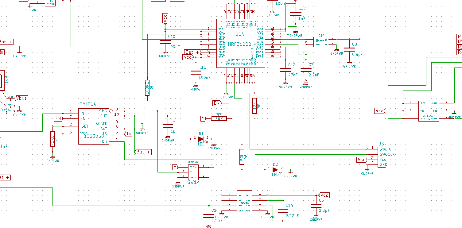
In our alpha board, we used the BQ25060 to charge our battery, we know that there are some problems with schematics, but the behavior of the PMIC is surprising and not expected, When we plug a USB cable to power the board LED D1 turns on for a moment and turns off again, then when we measur OUT pin of the PMIC, we find 0V (0.002V), when the USB is just pluged the voltage goes to something like 2.XXX V very quikly and then returns to 0V.
I checked the EN pin the voltage their is between 0.6 and 0.7V which means USB500 mode.

I connected TS to ground no results, and then used the recommended resistors between TS and LDO using the same values of the BQ25060 evaluation kit but still no results.
Could the problem be caused by SW1 ( NXP Analog switch : NX3L1G66) ?

Any idea or help is welcomed, thank you.

  • Hello Tarik,

    Could you please provide a schematic that is a bit clearer. When I zoomed in, the text became too distorted to read. A couple things I could make out are as follows:

    -The CHG pin is pulled low when charging. If D1's purpose is to signify the IC is charging, D1's polarity must be flipped (cathode to CHG) and be pulled up on the other end (anode to PU resistor, PU resistor to VCC. In this configuration your LED will turn on when the IC is charging your battery.

    -EN is an input. The voltage it may display is likely a poor indicator of what the IC may interpret. When EN is driven HI, the IC will be completely disabled. If you would like to control the charge current via a resistor on the ISET pin per your schematic, EN should be shorted directly to GND. If you would like to only operate in USB500 mode, EN can be left unconnected putting it into HI-Z mode. If you would like to take advantage of all three of these modes, your output pin of U1A that is connected to EN must be able to switch LO to HI to HI-Z. This behavior is referenced in pg. 14 of the datasheet.

    -LDO simply regulates to 4.9V when your VIN is valid. What you decide to load this pin with likely won't impede the function of the IC.

    My questions for you:

    Which of the three charge modes do you wish to operate in? USB500, Charge Disable, ISET controlled.

    Do you wish to monitor the battery temperature using the BQ25060?

    Could you provide a clearer schematic and I'll get back to you as soon as possible.

    Regards,

    James


  • Hi James,

    Thank you for the answer, I agree with most of what you said, that was an alpha board donne in few hours so there are many schematics problems.

    As for your request, we want to work with the USB500 mode so we should leave EN floating, we don't need to monitor battery temperature for this prototype, and we wish to use our board only 2 LEDs ( a blue one and a red one) :

    The red LED should be on in the following cases :
    1) when the battery is weak and the system is on.
    2) When the battery is in charging mode and isn't full yet, even if the system is off. 

    The Blue LED should be ON only in the following cases:

    1) battery not weak when system is ON.
    2) Battery charging is finished even if the system is OFF.

    Finally what do you think could cause the strange behavior I mentioned in the first post ,of having always 0V in OUT pin.

    7043.schematics.rar

  • Your battery should always be connected to your OUT/BATT thus OUT will always be whatever your battery voltage is. Also you wish to not use the TS function on the IC, you must provide a reference to the TS pin that makes it think it is always at a valid temperature. An example is provided in the EVM data sheet. If you ground the TS pin, the IC will believe the battery is greater than 45 degrees celcius, thus suspending charge current. The LED's desired function can be arranged once you are charging correctly.

    The only way to get 0V on OUT is to either not connect the battery or connected a completely discharged battery and disable the IC.


    -James

  • Thank you James,

    With the BQ25060 EVM I got a non 0V value at OUT pin even without connecting the battery,

  • Hi.

    I am facing the similar problem. Please let me know how you did you resolve the issue.