This thread has been locked.

If you have a related question, please click the "Ask a related question" button in the top right corner. The newly created question will be automatically linked to this question.

LM25117 Vcc supply

Other Parts Discussed in Thread: LM25117

Hi,

I am designing a power supply for the following:

Vin=20-30V

Tambient=105degC

Vout=13.5V

Iout=2A

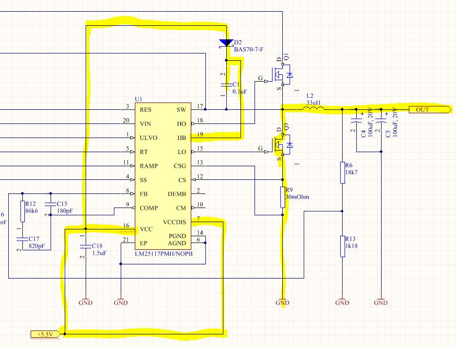
The choice fell on the LM25117. The question I have is on the Vcc supply source. Our application needs to deal with connecting the output of the regulator to a 27V source (automotive application). Would the chip be OK. We have the ability to detect high voltage on the supply line and disable the controller. Since there is a chance that the output of the reg. can be connected to a 27V source, powering the Vcc from the output is not possible (15V Vcc pin limit). We can supply external Vcc of 5V. Would the design still be ok? 

Another question is that if we use this Vcc to supply pin HB via a diode and if 27V is connected to the output (essentially SW pin) would it destroy the chip? (HB to SW limit of 15V from datasheet). Is it correct to supply the HB pin from the output (13.5V) and the Vcc pin from a different supply (this is to satisfy the HB to SW limit)?

I have another question:

I ran the WEBENCH for LM25117: with the following input:

Vin=32-36V

Vout=25V

Iout=2A

The resulting design uses the internal regulator (therefore the HB pin is 7.6V). How is the limit of HB to SW not exceeded in this design,

Please let me know if you would like to see the schematic of the design.

Regards

Witold.

  • Hi

    5V external VCC supply is okay.

    There is internal diode connection from SW to HB. If SW increase to 27V, HB will follow and be increased.In this case, the HB diode is  reverse biased.

    If SW is grounded, HB will be charged to 7.6V- 1 diode drop through the HB diode. If SW is biased by pre-bias source 25V, HB will be charged to about 25V through the internal diode path from SW to HB.

    Regards,

  • Hi Eric,

    Thanks for this information. 

    So, if my understanding is correct, the HB pin is supplied with 5.5V - diode V (in the schematic) only until the controller is working and after this time the it will be supplied from SW. Would you comment on the Vcc supply connection in the schematic below?

    In the condition that 27V is fed into the output of the controller, will it shut down the low side driver, by detecting the high voltage with feedback resistors, or will it only detect the overcurrent and shut down the controller then (this would relay on the low side driver and current sense resistor being capable of handling the current before shutdown).

    Best Regards

    Witold.