This thread has been locked.

If you have a related question, please click the "Ask a related question" button in the top right corner. The newly created question will be automatically linked to this question.

BQ34Z100 VEN ON with REG 30mA Current . Why increase Current at VEN ON ??

Other Parts Discussed in Thread: BQ34Z100

Hi

I have some question for BQ34Z100 Spen.

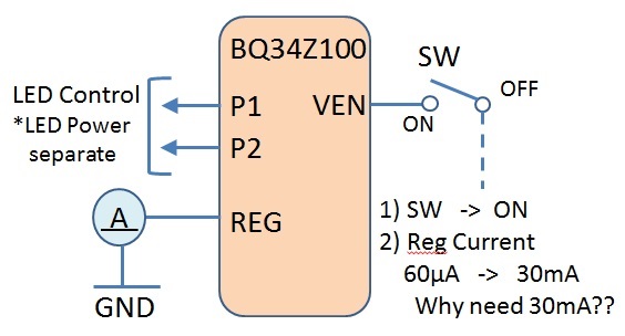
This device has LED indicater as Gage Staus.

Now Our sysytem use 10 LED indicator for Remain Gagae.

But we found this pehnomenon and dupulicate step 1 ) - 3)   

Step 1)   VEN  ON

Step 2)  We messurement for Current  between  Reg and GND

Step 3)  Result  is  30mA   at   VEN ON        *   Normal  VEN  OFF  =>  60uA

【 Question 】

 Why current increased to 30mA  from 60uA ??

  Of course,  LED Power seperated  from this REG Power Line.

  Could you tell us about this reason ?  Dose thise device need  30mA Curent with LED Status ??  

  Could you tell me  this REG current spec?

  Because of,  we dose not have this device Bloack Diagram and deatial.


Regard

Jasper


  • Jasper,

    We recommend placing a 1 kohm resistor in series with the switch connecting REG15 to VEN to limit the current. Please reference the schematic in Figure 7 of the bq34z100 datasheet.

    Regards
    Tom

  • Dear Tom 

    Thank you very much quick replay.

    I will try and need test with 1k ohm resister. 

    Thanks and Regard 

    Jasper 

  • Dear Tom 

    Now  I used  BQ34Z100  EVM and measured current about this REG Current 30mA  Issues. 

    【 Question 】

     Dose BQ34Z100 EVM has this 1k Ohm on EVM Board?? 

     Because of  I could not found 1k Ohm Resister at VEN on EVM.

     But Data Sheet schematic has this 1k ohm as R38.

    And  we need Reason for this phenomenon and  cause relation between VEN 1K Ohm and REG.

    I think this is some relation to internal function block .

    For Instance

        VEN  Function  is  Open Drain or   Push Pull  .... or something.

    Regard

    Jasper 


  • Hi  Tom 

    I checked  REG25 Current with  this Resister between 1K  and 10k Ohm.

    Resister Value(ohm)          REG2.5 Current (mA) 

         0   ohm                                32.8mA

        1k  ohm                                4.25mA

        5K ohm                                2.38mA   

      10k  ohm                               2.13mA   

    We wants  Maximum Resister value for VEN .

    Because of we need save consumption current at LED Gage Status.  

    Could you tell us about this Maximum Resister Value? 

    Thanks and Regard

    Jasper 

  • Jasper,

    I did not conduct the original analysis to select the resistance value. I an out of the office through Friday, but I will look at it next week. Also, the resistor was added to the newer version of the EVM. You must be using the old one.

    Tom

  • Dear Tom 

    Thank you very much.

    We want to know just these one.

    1)   Why relation this REG25 Current increase with VEN  Resister setting (= Current setting ) ??

    2)   Could you tell us about VEN internal Function ??      Pushpull , or Internal Pull Down Resister value.... etc. 

    3)   About this resister setting finale value decide by  High Level keep  minimum current for VEN.

         This mean  , almost device has V_IL , V_IH, I_IL and  I_IH spec.    I think need I_IH spec  VEN for this device.

    Any way can I contact  to you directory??

    Regard

    Jasper 


  • Jasper

    My testing shows that the device requires 75uA to be forced into the VEN pin to be recognized as a high level and turn the LEDs on. That will limit the series resistance to about 33 kohms.

    Tom

  • Dear Tom 

    Thank you very much.

    Thanks and Regard

    Jasper in Japan 

  • Dear Tom 

    Thank you very much about this Resistance and Current Value.

    But we need more some information about this Answer.

    Question 

    1)  This VEN Port internal easy Block and Structure.  * What type input Port structure? 

        Because of we need how to calculate about this Resister value with Min Current. 

    Thanks and Regard

    Jasper 

  • Jasper

    The pin has a totem pole output structure to provide gate drive to the external FET network that disables the BAT sense circuit when the voltage measurement is not in progress. The pin also have an analog input buffer and you have to force current into the pin to overdrive the internal low-side FET. The series resistance needs to be 33 kohm or smaller to overdrive the FET and actuate the LEDs.

    Regards

    Tom

  • Dear Tom 

    Thank you very much.  

    I understood VEN structure.

     Thanks and Regard

    Jasper in Japan

  • Hi,

    I am also trying to use the BQ34 in the led configuration : 5 leds ,I2C bus

    - Pack Configuraton = 0x0141

    - Pack Configuration  B = 0xFF

    - Pack Configuration C  = 0x30

    - Led_Comm Configuration = 0x43

    - Number of cells = 0x01

    The schematic to enable the I2C communication is quite similar to the one shown at page 46 of the  Bq34Z100 - G1 data sheet but when I press the button no communication occurs.Really  I don't understand what is my mistake .

    Moreover the VEN pin goes high every 1 sec. for about 150 mS and when the button is pressed I can detect the 2,5 V on one side of 1K resistor but on the other side (VEN)  I only see the 1 second transition of VEN pin

    Thanks

    Giuliano