This thread has been locked.

If you have a related question, please click the "Ask a related question" button in the top right corner. The newly created question will be automatically linked to this question.

bq28550 I2C Communication Problems

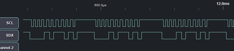
We are trying to establish I2C communication with the bq28550 Battery Gas Gauge and have been having some trouble. I'm personally new to using I2C, but I'm using some modules that we have used in the past to successfully communicate with other I2C platforms. I have several questions:

1. We have been unable to get the bq28550 to acknowledge a 'Quick Command' message, of the format: [Start] -> [Address] -> [R/W] -> [ACK] -> [STOP]. As a newcomer to I2C, I'd like to verify that the correct way to address the bq28550 (address = 0x16) followed by a 'Write' bit would be of the format:

[Start] -> 0-0-1-0-1-1-0 -> 0

and that this should be followed immediately by the bq28550 pulling the SDA line low in acknowledgement of being addressed. Please let me know if this is the correct addressing scheme for this device.

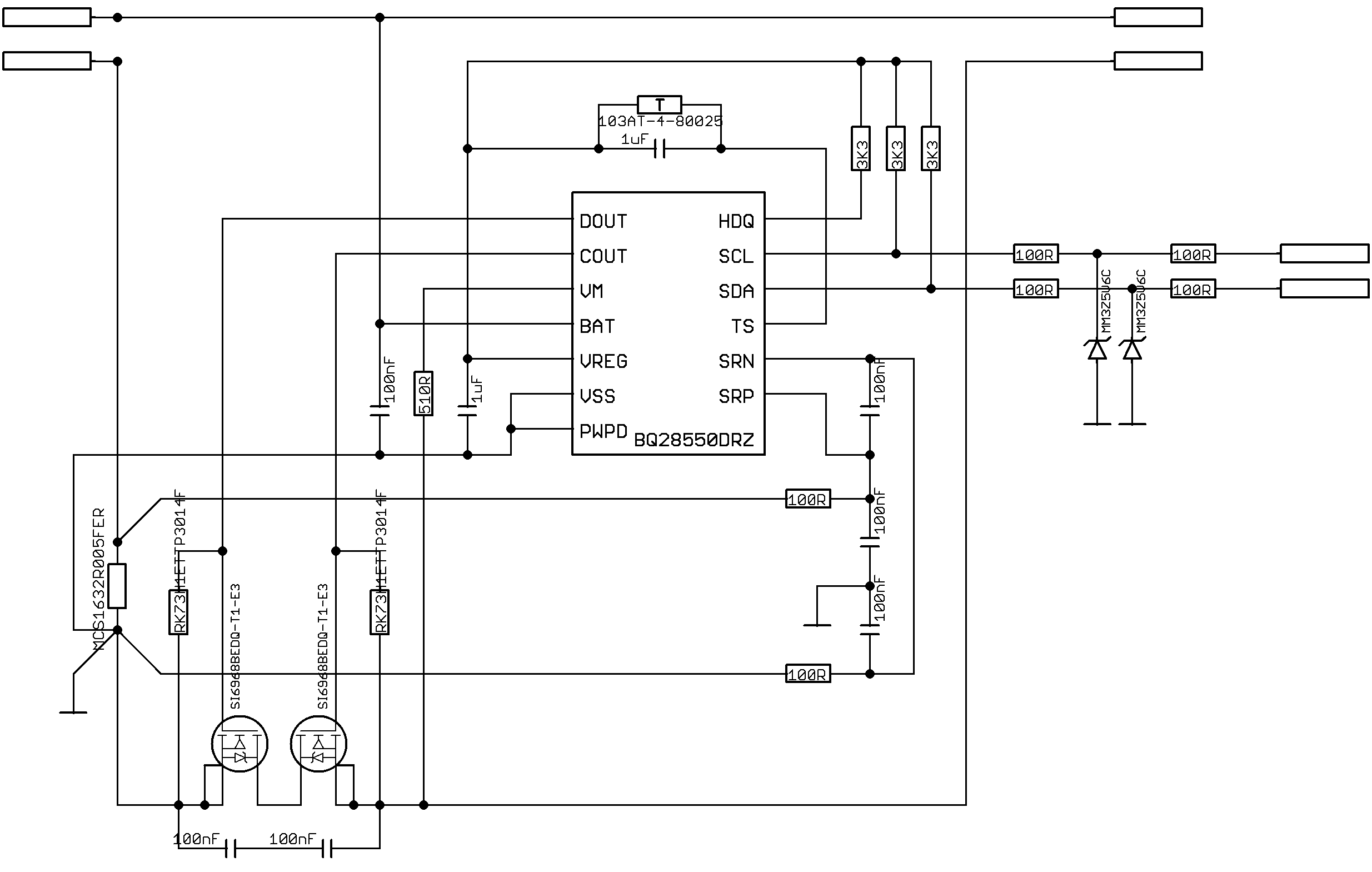
2. We have replicated the Reference Schematic in the bq28550 Datasheet, with 3.3k resistors pulling up the SDA and SCL lines to VReg (2.5V) and 100R resistors in series with the bus going out of the board. Our I2C module acting as the master uses a 2.8V supply pulling up the SDA and SCL lines through 10k resistors and no series resistors. As best as I can tell, this would not negate successful transmission, but please let me know if this is wrong.

As far as I can tell from the SMBus specifications, all of our timing and voltage levels on the bus lines are acceptable. Please let me know if these or any other common problems could be impeding us. Thank you.

  • Still have not had any luck communicating with the bq28550. Both the Charge and Discharge MOSFETs are on (DOUT=COUT~=4.2V). As far as I can tell from the Data Sheet and Technical Reference, if both of these are activated, bus communication should be enabled; please correct me if I am wrong. Because the 0x16 slave address did not give us any response, I wrote some code on the Master to increment through every possible slave address (0x00-0xFF) to try to get an ACK response from the Gas Gauge. The program runs in a constant loop, putting the following message on the I2C bus:

    [Start Condition] -> [Address] -> [R/W Bit] -> [Read SDA for ACK] -> [Stop]

    We are never receiving an Acknowledgement bit from the bq28550 for any address. All timing and voltage levels of the SDA and SCL signals appear to be within the SMBus 1.1 specification. We have tried this with multiple ICs and get the same behavior. The bq28550 is powering the host that is querying it on the I2C line. Please let us know if there is any reason the bq28550 would not be responding to I2C messages, or if the format of the messages needs to change.

  • It should be noted that we have not included transistors Q3-A/B (from the Reference Schematic in the Data Sheet) in our design and have left pin 12 (HDQ) of the bq28550 open, because it was mentioned on these forums that HDQ has no functionality on this Gauge. Is this true? Could this be hurting our bus performance?

  • Hi Brenton,

    The sequence is for a write is:

    [Start] -> 0-0-1-0-1-1 -> 0 and not as you currently have it.

    for a read is

    [Start] -> 0-0-1-0-1-1 -> 1


    let me know if this helps

    thanks

    Onyx

  • Thank you for the reply Onyx, it is appreciated. The 6 bit addressing you described does not appear to be working either; the slave is still not sending the ACK reply.

    I have noticed that there is a ~150mV square wave showing up on the bq28550 VM (pin 3) which is inverted from the SCL line, i.e., while SCL=2.5V, VM=0V, and while SCL=0V, VM=0.15V. We cannot explain why this is happening, since the SCL and VM pins have no external electrical connections. In the bq28550-R1 datasheet, page 16, it says the device will detect and a discharge overcurrent condition when the VM pin is higher than 0.15V for longer than 12ms, and that this will turn off the DSG transistor to stop discharge, and that bus communication will be disabled.

    In our case, VM is only higher than 0.15V for a few microseconds, and it doesn't appear to turn of the DSG transistor. Could it be temporarily disabling bus communication for the short time it is higher than 0.15V? It should be noted that we have left out the connection between HDQ and VM through transistor Q3 shown in the 'REFERENCE SCHEMATIC' on page 33 of the bq28550-R1 datasheet, because we did not intend to use the HDQ. Could this be our problem? We would like to be sure before we redesign our application.

  • Hi Brenton,

    That was a typo on my part. What I intended to write was the seven bit address followed by either a write or read eg

    [Start] -> 0-0-0-1-0-1-1 -> 0

    pin 12 is a GPIO pin used to control the CFET using firmware. If it isn't used, it should be tied to Vreg externally. Kindly reference the data sheet. I don't think that the HDQ functionality of pin 12 is in operation. 

    Can you share your schematic?

    thanks

    Onyx

  • Thanks Onyx. This did not seem to solve the problem either. In the attached image, you can see the Logic Analzyer's capture of the signals into the bq28550's I2C bus. It transmits the correct address, followed by a 'read' bit, but does not receive ACK, and continually does this on a loop. Both the charge and discharge transistors are turned on at this point, and the bq28550 is powering the I2C Master:

    Also attached is our application schematic. As far as I can tell it matches all of the critical functions of the Reference Schematic, but please let me know if you see any problems:

  • Hi Brenton,

    Nothing on your schematic appears as an anomaly to me. Here is what I suggest you do:

    Connect your device to an EV2300 and connect to a computer. Download and install our EVSW for the bq28550 and check to see if you have communication with the device. On the EV2300, make sure the device is connected to the SMB port. If you have communication with the computer, then it means your devices are  ok.

    Also can you connect your lines to an oscilloscope intead of the logic analyser. This will enable us to see if your host is pulling the lines high when the chip is trying to pull it low.

    Your logic analyser image above shows the address is correct. Keep it that way moving forward. It's hard to tell from your logic analyser image, what the frequency of your I2C signals is. Can you let me know?

    thanks

    Onyx

  • We have resolved the issue now; our pull-up voltage was different from the bq28550's. Onyx, thank you for all your help.

  • Hi Brenton,

    I'm having the same issue as you. Could you explain more about how you solve it?

    I build the b128550 with a msp430 together so the schematics are not exactly identical to the reference. But i use pull up to 3.3V from the msp430.

    Thanks

  • Vreg which the bus lines are pulled up to on the EVM is 2.5V

    -Onyx