Dear Sir
Good days,
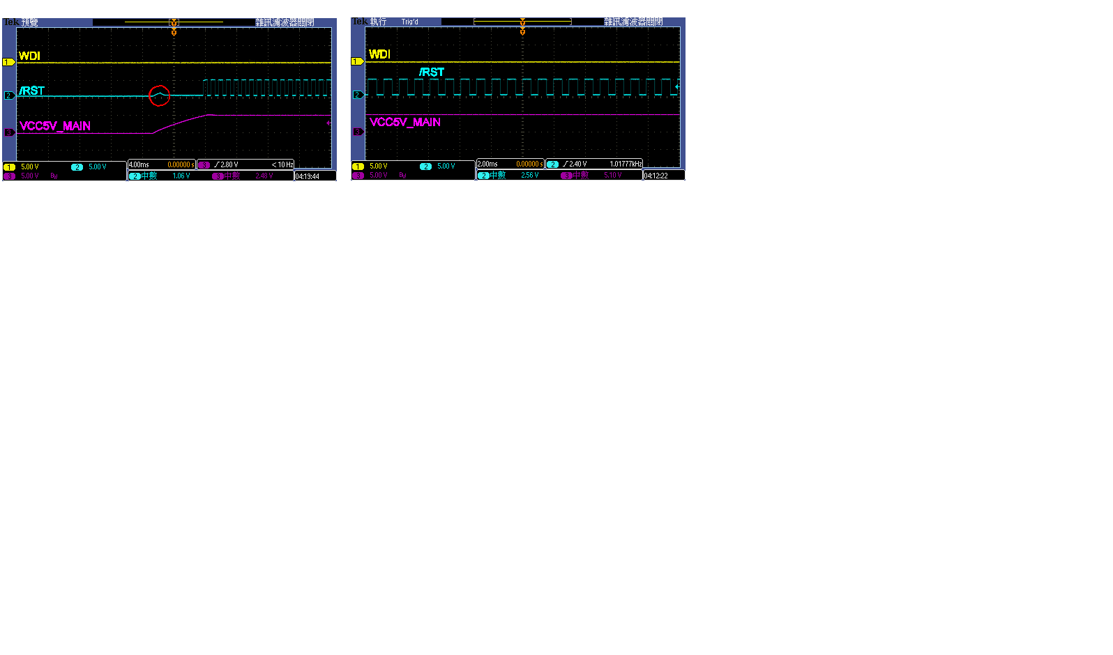
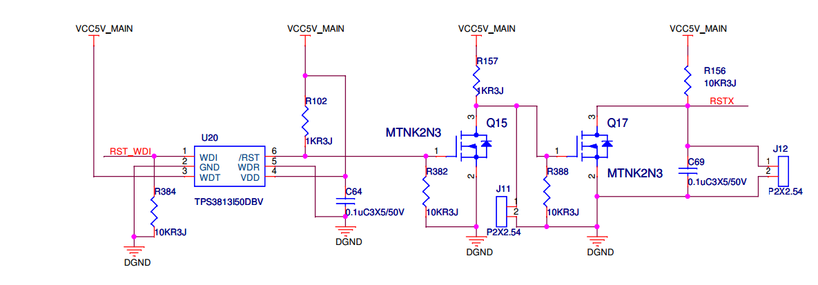
Here have one question that when we add 470uF capacior in VCC5V_MAIN, then reset will have plus output.
may you pls advice us what parameter i loss?

Best regards
Bogey
Dear Sir
Good days,
Here have one question that when we add 470uF capacior in VCC5V_MAIN, then reset will have plus output.
may you pls advice us what parameter i loss?
Best regards
Bogey