This thread has been locked.

If you have a related question, please click the "Ask a related question" button in the top right corner. The newly created question will be automatically linked to this question.

TPS54260, about simulation model and problem while using it as Dc-Dc convertor

Other Parts Discussed in Thread: TPS54260

Hi,

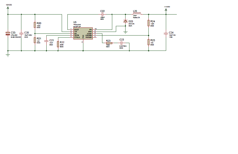
Anyone can help me please, from where I can get TPS54260 model  + necessary library files  for the purpose of step down DC-DC converter. (had one model downloaded from TI side but it is with 5 pin, is it possible to get 10 pin model ), Any idea?

Problem with TPS54260 while using it as DC-DC converter. Takes DC input of 28V and designed to give 12 V DC as output. But  the output is not perfect. 12 v DC output  have some noise / oscillation while analyzing output through oscilloscope. 

How  I can rid off this problem, any idea?

Your helpful suggestion are honorable to me. 

Kind Regards,

Syed Shah

  • Can you post your schematic and some waveforms that show your problem?

  • This is the only schematic file I have and soldered board is burned out, unable to get wave forms again . TPS54260  raised its temperature last time with attached schematic diagram  and burns out.

    Here:

     C33 = 470 uf

    C20 = 10 uF

    R20 = 105K

    R21 = 14K

    C21 = 10nF

    R22 = 205K

    C22 = 100 nF

    R23 = 7K68

    C23 = 8.2 nF

    L20  = 33 uH

    R24 = 130 K

    R25 = 10K

    C24 = 10 uF


  • Hi Syed,

    It sounds like you had downloaded the PSPICE Average Model which can be used for frequency response and generates bode plots to check loop stability. There is also the PSPICE Transient Model which can be used to check how the device operates with respect time during start up or steady state.

    Best Regards,
    Anthony