This thread has been locked.

If you have a related question, please click the "Ask a related question" button in the top right corner. The newly created question will be automatically linked to this question.

Start-up problem with TPS54040A

Other Parts Discussed in Thread: TPS54040A

Hi all,

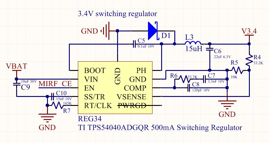
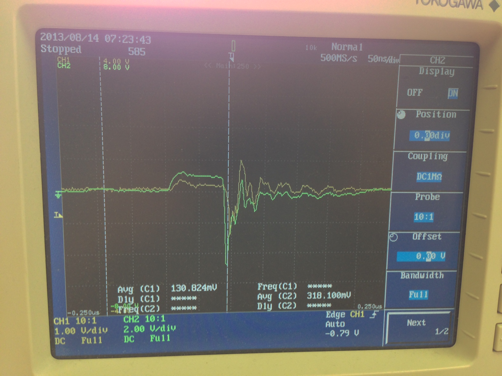
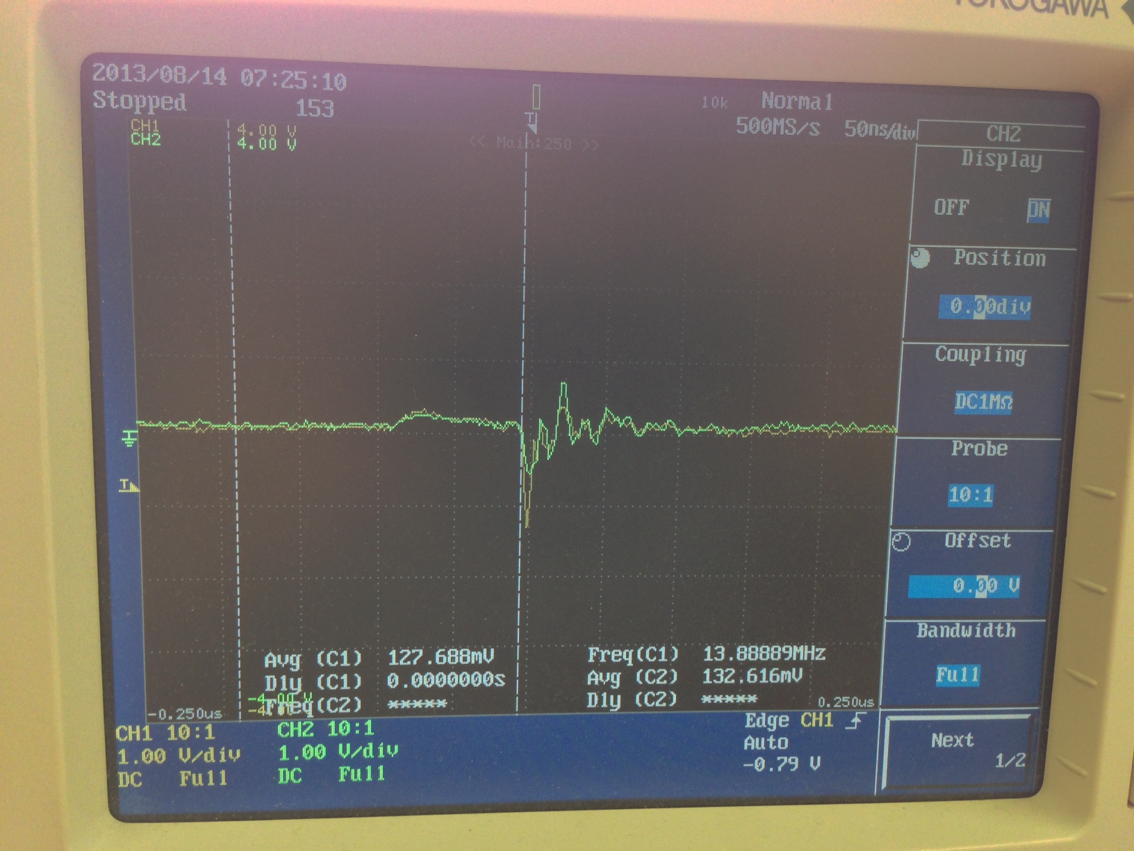
I have assembled (using the TI design tool) a TPS54040A-based switching circuit with 3.4-3.5V out.  I have built two boards and checked all of the components and connections on them, and I am seeing the same result on both - when EN is held low the device is very much off and drawing no current; when I switch it on (with 15V in) it draws 70-100mA and outputs little 0.4V bursts on the output line every 12us or so.  I'm not sure what is going on here - any thoughts?  Schematic and scope output below.  D1 is MBRA340T3G, L3 is TDK VLCF4028T-150MR88-2.  Thanks!

  • Hi Robert,

    I'll move your posting over to the Non-isolated DC-DC Forum so you can get the right Apps support.

    Best Regards,

    -Juan

  • If you have no load connected you are operating in pulse skipping eco-mode.  try attaching enough load so that you are operating in DCM .  You should then have a regular pulse train on the PH node.

  • Hi John,

    Thanks for the response.  I have tried this with no load, a 200 ohm load, and a 67 ohm load with the same result.  Isn't this supposed to be able to handle a few hundred uA load anyhow without losing regulation?  Thanks.

  • Hi,

    Is there any more information I can provide to get to the bottom of this problem?  Any idea what it might be?

  • Eco-mode threshold is somewhat unpredictable.  You can monitor the COMP pin voltage to see if it is clamping at the low end (around 500 mV).  68 ohm is still pretty light, try 10 ohm.  That should put you well into normal operation and CCM.

  • Looking at your schematic, it looks like there is a drawing error that might be causing the Soft Start capacitor to be shorted out.  That would tend to prevent startup.

  • Hi Marc,

    I'm a bit confused by your comment ... I see C10 of 15nF going from Ground to SS/TR pin.  Isn't this the intended configuration?

  • If you look closely at the schematic, you can see that there is a black line across the plates of the SS capacitor.  This is probably a piece of net wire that was drawn incorrectly.  It may (or may not) be shorting out the capacitor.  To know for sure you can check the netlist, layout, or measure the resistance on the board.  On reflection, probably a short would have been caught in layout, so this is probably a red herring.  But ironic since it would seem that it might cause the behavior you're seeing.

    Otherwise, it looks like maybe it is trying to start up into a short circuit?  Check the resistance at the output with power off.  Also check that the catch diode is not reversed--that might cause the effect you are seeing.

    With power on, check the voltages/waveforms on all the pins, make sure they all make sense.

    Good luck!

  • Hi Marc,

    Thanks for the info.  The black line was indeed a drawing error but didn't make it into the circuit.  Here is the scope trace of the output and the COMP pin (green) - both have the same ground reference and scale.  I have verified the output is not shorted.  The catch diode looks correct as well.  Any thoughts?

  • Hi,

    Is there any other information I can provide to get to the bottom of this issue?  I'm not sure what the COMP pin output in green above is supposed to be telling me...

  • If I read that correctly, Vout is near 0V, and COMP is about 1.7 V.  With Vout low, COMP is (and should be) railed out at 1.7 V.  That should be commanding a high duty cycle.  What is the BOOT voltage?  If it is not 6 V or so above PH, then the highside cannot turn on.  What is SS?  If it is low, then it will not start up either.

  • BOOT pin is green, referenced to ground

    PH pin is green, referenced to ground

    SS pin is green, referenced to ground

    Looks like BOOT is coming down pretty hard at the switch attempt?  I have 0.1uF spec'd, with my meter I am reading an actual value with power off of 93.5nF, which sounds like it should be OK?

  • It looks like the SS pin is at zero volts?  That would keep the chip from running.  Measure the resistance from SS to ground with the power off.  Use the scope to watch that pin as either power is applied or the EN pin is brought high.

  • Hi Marc, thanks for the help.  SS to ground is 1Mohm+.  Scope trace is green above at power-on.  Looks like it's going up to 0.45V or so and then coming down to rest around 0.1V.

  • It looks like it is trying to start but then shuts down, perhaps due to overcurrent.  Check to make sure that the EN pin is solidly high the whole time.  And are you absolutely certain the the diode is not backwards?

  • I don't think over current can cause a shutdown, but is has been a couple years since I last looked at this device.  Yes check EN and VIN to make sure you are not tripping UVLO.  Then you can try manually raisin SS with an external supply.

  • All very strange...

    Here are plots of EN and VIN, respectively:

    If I reverse the diode, I get 10V on both SS and EN, and 0.7V approx output.  This is not exactly what I expected for 'correct', but looks better, so I looked into the issue further.  And bam, apparently I'm an idiot.  I took the TPS54040A pin 1 marker as the diode marker...  That's what I get for cramming everything together.  See here:

    I think that board has some sort of short as the other one doesn't go to 10V on SS and EN when you power up.  Here is the plot of VOUT (yellow) and EN (green) on the 'good' board:

    Definitely looks like 0.7V or so output.  Current draw is around 4mA in enabled, and maybe a dozen uA when disabled.

    Thanks for all the help thus far!

  • I have double-checked that the resistor divider values are correct - in-circuit they measure about 7.7kohms, but removed they measure a reasonably correct 10kohms and 33kohms.

  • Are you sure that all the compensation components are installed on the correct pads?  Looking at the layout it seems like it might be possible for those to become confused.  Also the chip has a thermal pad that must be connected to ground.  The copper is there in your layout sample, but are you sure that there is a soldermask opening and paste applied?  If this board was not reflow soldered, it could be tricky to get the thermal pad soldered.  And looking at the layout in general, there are a lot of floating pieces of copper (e.g. under the inductor) that would probably be better to not have, copper between the pads of SMD componenets that might lead to solder bridges, and perhaps more ground vias than necessary.

  • Hi Marc and John,

    Thanks again for all your time.  I have apparently resolved the issue.  I found the short on the other board that was causing EN to go to 10V - it was due to bumping the IC during hot-air flip of the diode.  After running this one, I am seeing 3.43V solidly.  61mW out into 195 ohm load, 92mW in, not bad for light load.  If I remove the load, I get 180-190uA in regulation, with regulation sticking around 3.38-3.47V.  So I think we can call it resolved.  Thanks guys!!!

  • I'm glad you found your issue.  Thanks for using the e2e forum.