Unintentionally I closed my question before solving. Then I post again.
----------------------------------------------------------------------------------------------
Hi, I'm using TPS40210DRCT for 12V regulation circuit from 5V.
The load is approx. 2A but cyclic (F=200Hz).
It repeats like below.
2A (2ms) -> 0A(3ms) -> 2A (2ms) -> 0A(3ms) -> 2A (2ms) -> ...
But when the load gets active, GDRV doesn't react immediately. It starts driving after 50us from load gets active.
Then during no regulation period (50us), 12V drops to less than 11V. And after 50us, GDRV starts toggling.
But in order to compensate dropped voltage, an inductor current gets much higher than usual, around 9A like inrush current.
In consequence, the inductor sounds at 200Hz.
Do someone know the reason why GDRV doesn't start regulation for 50us, even 12V drops so much?
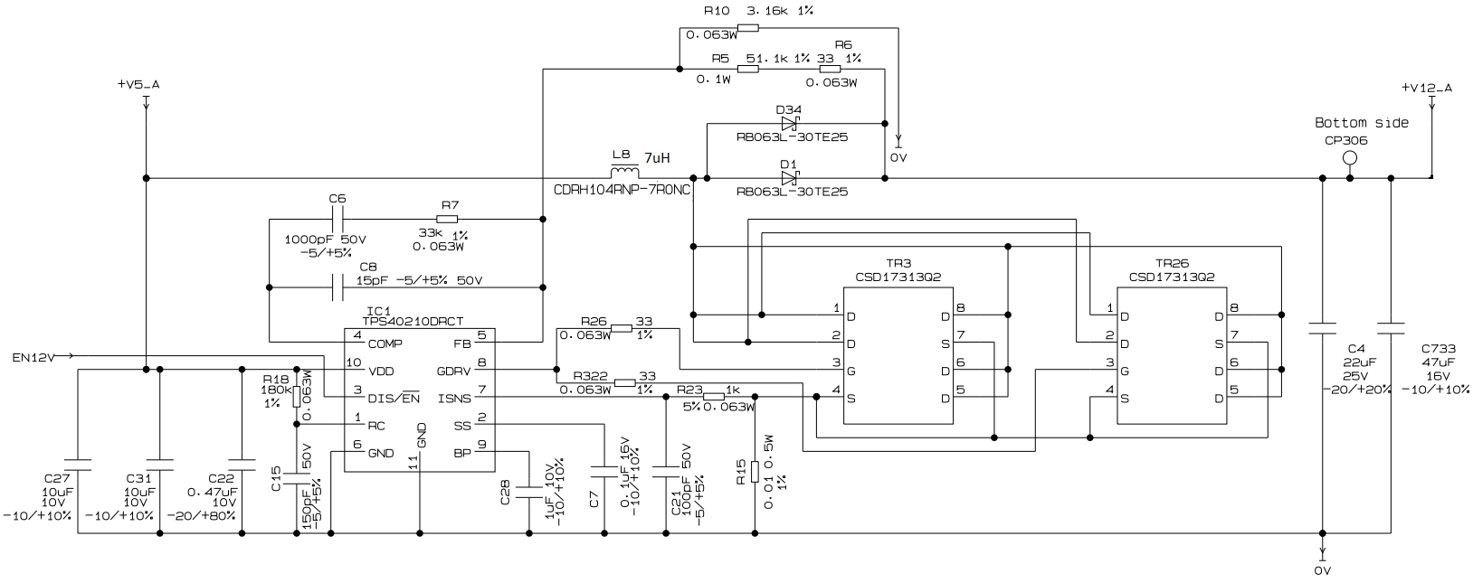
[Schematic]
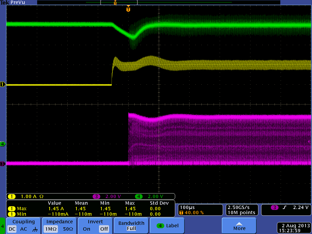
[Waveform]
4.Green: 12V
1.Yellow: Load (it is not 2A but 1A.)
3.Red: GDRV