This thread has been locked.

If you have a related question, please click the "Ask a related question" button in the top right corner. The newly created question will be automatically linked to this question.

Regarding TPS3828-33 watchdog IC

Other Parts Discussed in Thread: TPS3828

Hi,

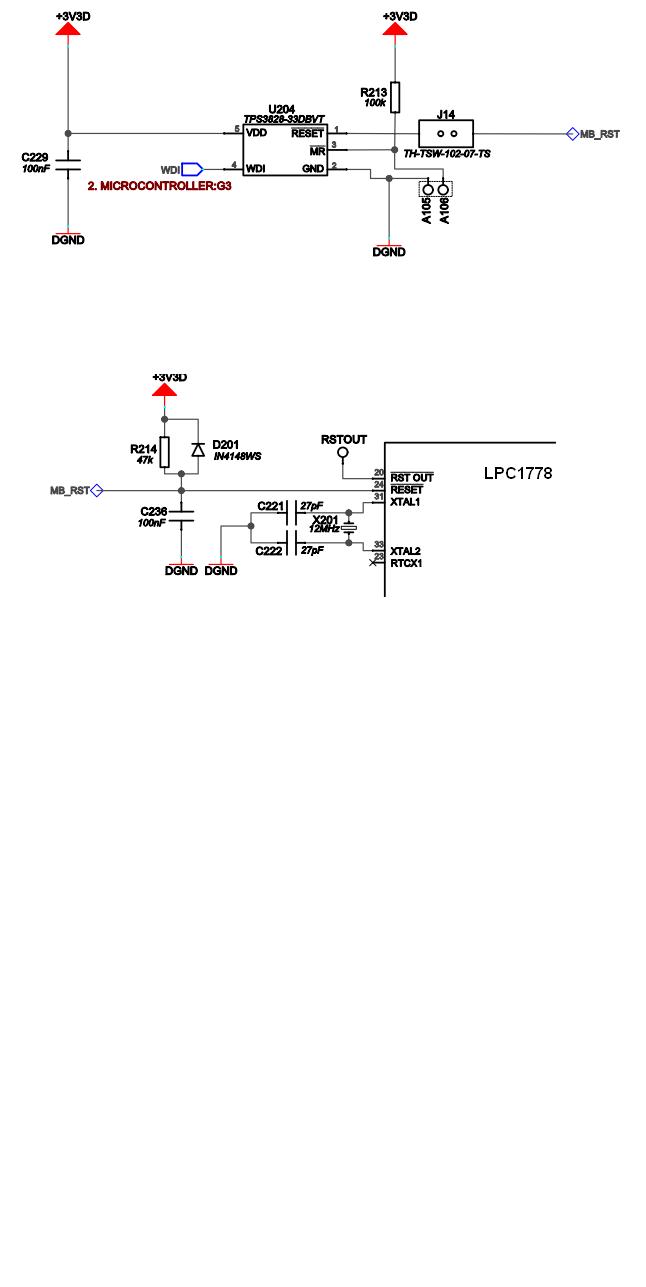
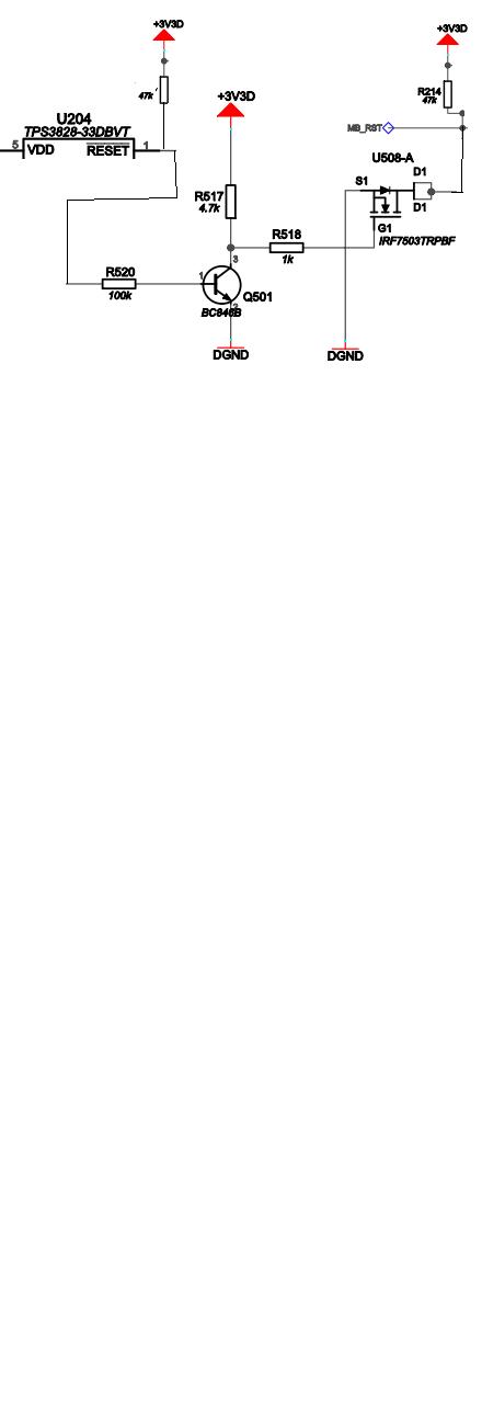
  I am connecting the watchdog IC to reset pin of LPC1778. When the watch dog serving is stopped by the microcontroller the RESET of TPS3828 has to go low, but instead of going to 0V, it is coming only till 1.9V. But when I separate the the reset pin of watch dog and micontroller using a transistor switch the transistion is fine. The reset pin in the microcontroller has an internal pull up of 50k ohms. Kindly provide a solution as soon as possible.

Best regards

Ajith

  • Hi Ajith,

    If you look at page 7 of the datasheet, to get a VOL of 2V, the current is about 6mA. When the load is removed, current is 0mA which is why VOL is 0V. You must reduce this current in order to lower the VOL voltage. Do you have a schematic of your application that we can look at?

    Regards,

    Darwin

  •  Hi,

        Kindly see the above schematics what I am using. In this i have removed the diode  and capaicitor as well near the microcontroller. I have also tried with 100k and 10k instead of 47k. Then also it is not coming proper. KIndly advise.

    Best regards

    Ajith

  • Hi Ajith,

    I don't see anything initially wrong with the SVS. One thing to check to see if it's the micro or the SVS is by completely remove the load from the SVS and see if the TPS3828 operates correctly. Open circuit J14. Is the MB_RST connected to any other load? What does the circuit look like when you decouple RESET with a transistor. Do you have a waveform showing MR, WDI, RESET, and VDD during the 1.9V LOW? Could you check the GND connection of the SVS to see if it's fully soldered on?

    Regards,

    Darwin

  • Hi Darwin,

               When we open circuit J14 and connect a pull up resistor to the RESET pin of Watch dog IC it is working fine. So I implemented a circuit instead of Jumper J14 as shown below.


    At this time it is working fine. The ground connection is fully soldered on. Kindly advise.


    Best regards

    Ajith Sasidharan

  • Hi Ajith,

    Having to decoupling the output of the TPS3828 from the uP in order to operate correctly leads me to believe that there is some excess current into the pull down FET in the TPS3828 from the load causing the VOL voltage to increase. You can easily verify this by measuing the current through J14 (without the above external circuit) with a current meter. Looking at Figure 5 of the datasheet, the current that creates a VOL of 1.9V is around 5-9mA into the RESET pin of the TPS3828.

    Regards,

    Darwin