This thread has been locked.

If you have a related question, please click the "Ask a related question" button in the top right corner. The newly created question will be automatically linked to this question.

LM2595 Minimum Load Current

Other Parts Discussed in Thread: LM2595

Hello,

I have never used a switching voltage regulator before and I decided to try and design a circuit with the LM2595. I have a question about choosing the right inductor. The input is 24V, the output 5V, and my load can vary between about 20mA to 350mA. I don't care about board space or efficiency, but I do not want to have a lot of voltage ripple. What value of inductance do you think would be the safest bet, and also will I run into any regulation problems when the load current drops to a low value like 20mA?

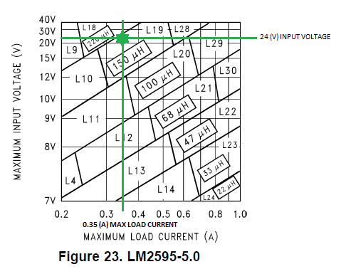
Originally I thought I would design the circuit to handle a load of 1A just to be extra safe and go with the 100uH L29. However, after reading a little it sounds like this lower inductance will make the voltage ripple higher. So perhaps the 150uH L19 or L28 would be better. Would an even higher inductance like 220uH provide even less ripple if it was designed to handle the current?


Thank you so much for your help!

Hunter

  • Hi Hunter,

    While the inductor does play a role in Ripple, what you're looking for is adjusting the output capacitor.

    The basic selection of the output capacitor is based on the ripple current and ripple voltage, as well as on loop stability considerations.

    The effective series resistance (ESR) of the output capacitor and the inductor value directly affect the output ripple voltage. The output ripple voltage can easily be estimated based on the inductor ripple current (ΔIL) and output capacitor ESR. Therefore, a capacitor with the lowest possible ESR is recommended. For example, 4.7- to 10-μF capacitors in X5R/X7R technology have ESR values of approximately 10 mΩ. Smaller capacitors are acceptable for light loads, or in applications where ripple is not a concern.

    The inductor value can be selected based ont eh graphic you attached, however the current rating of this inductor should be 30-40% higher than the maximum current of your application. This allows the inductor to factor in the current ripple. This ripple is then passed through to the capacitor, where ESR plays a role in increasing both losses and voltage ripple.

    Vripple= Vo(1-DutyCycle)/(8*freq^2*L*C)

    Where L= inductance and C= capacitance.

    For the LM2595, you can put your operating ranges into WeBench, the TI tool to calculate your schematic and simulate results. It will help you figure out the capacitance and inductance you require.

    Hope this helps!

    Thanks,

    Anston

  • Thank you very much for your response, that answers most of the questions I had. It is interesting how much the actual capacitance of the output capacitor varies. The data sheet table indicates a 120uF/25V Nichicon PL series electrolytic. However,  WeBench chose a 220nF/50V multilayer ceramic capacitor from TDK for my design. I guess that like you said ESR is the primary factor to consider. 

    My last question is how would  a switching regulator like the LM2595 operate if the load current dropped to 0A? Will it still be able to regulate effectively without a load, and will the ripple voltage increase or decrease?

    Thanks,

    Hunter