This thread has been locked.

If you have a related question, please click the "Ask a related question" button in the top right corner. The newly created question will be automatically linked to this question.

BQ25504 Vbat_UV and OV connected together

Other Parts Discussed in Thread: BQ25504

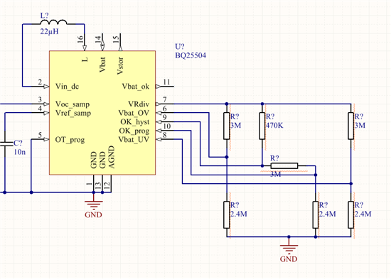
I'm designing a Solar 3.7V lithium charger with the BQ25504 and a 0.5V/100mA solar panel.

I selected common resistor values to obtain acceptable results. (Not fully complying with the 10M-rule)

MPPT = 0.751

Vbat_uv = 2.81V

Vbat_ov = 4.21V

Vbat_ok_prog = 2.81V

Vbat_ok_hyst = 3.03V

* The voltage divider for UV en OV is the same, can these 2 inputs tied together to save 2 resistors? The HIGH-LEVEL FUNCTIONAL BLOCK DIAGRAM shows that these 2 are inputs for a comparator, which suggests it is possible.

* Can the Rok3 be shorted, and not using the hysteresis function for Vbat_ok? By connecting VRdiv to OK_hyst, gives the possibility to leave out 3 additional resistors.

  • Regarding tying VBAT_UV and VBAT_OV  to same resistor divider, I do not recommend it.  The IC turns off the FET between VBAT and VSTOR when the voltage is below VBAT_UV setting so, at best, the battery may never charge more than a diode drop below VBAT_OV setting.  Charging a Li chemistry between below a certain voltage is generally not recommend for safety and battery longevity.  However, if you want you can tie VBAT_UV to VSTOR to disable VBAT_UV and have the FET turned on all the time.

    Regarding disabling VBAT_OK hysteresis, you can connect OK_HYST to OK_PROG but VBAT_OK will likely switch every 64ms while the battery is slightly below and above the VBAT_OK threshold.

  • I want the UV and OV functionality as well as the Vbat_ok output.

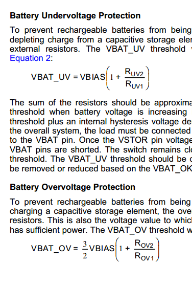
    Using the same resistor divider for OV en UV gives an 3/2 difference (See image with the Equations) in trigger voltage, or UV=2.81V and OV=4.21V (Which are good settings for a 3.7V Lithium battery).

    Since Rov2 = Ruv2 and Rov1 = Ruv1, I though I could connect them together as the internal compare voltage would be different (?). I do not indent to set the Over- and Under-voltage to the same level. I want a 2.81V * 3/2 = 4.21V als voltage trigger levels, which results in an identical voltage divider for both signals.

    Toggling the Vbat_ok signal every 64ms is indeed not wanted behavior. Doesn't the BQ provide an internal 50mV hysteresis if it is not externally done with the resistor divider?

  • Although we haven't tested this, using the same divider for UV and OV should not cause a problem.

    The internal 50mV hysteresis may be enough to prevent the VBAT_OK from togglling if the battery charges more than 50mV in 64ms.