This thread has been locked.

If you have a related question, please click the "Ask a related question" button in the top right corner. The newly created question will be automatically linked to this question.

bq34z100

Other Parts Discussed in Thread: BQ34Z100, BQEVSW, BQ24105

hello,

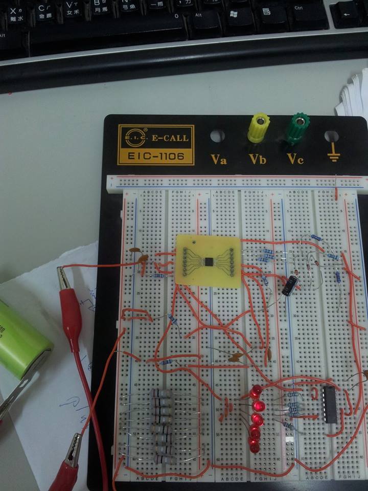
          I use the IC bq34z100 to detect the capacity  of  1S  LiFePO4 ,  and the circuit  I  referenced the datasheet

Figure7. 1-Cell Li-Ion and 5-LED Display  ,  I am not sure the circuit will be work or not.  And the first problem I met

is that  there is the BAT+ ,BAT-,and PACK-  at  the circuit ,but I only have one battery.So,if I connect the

battery Positive to BAT+,and battery Negative to BAT-,  the PACK-  is connected to ground.   and  I measure the

voltage at the sense  resistor  is zero ,and the voltage of SDA,SCL are both zero, I don't know what the problem is

and how to improve my    circuit.      Thank you all.

                                                                                                                                                    LYS 

  • Make sure that the VOLTSEL is set to 0 in the Pack Configuration register and Number of series cells register is set to 1. Make sure that the jumpers on the EVM are set to the two <5V positions on J5. The voltage at the sense resistor should be about 0V, but the voltage on the SDA and SCL signals should be close to the cell voltage.

  • thank for reply

    because my  circuit  isn't  the EVM.   I think there are maybe some problems  on the circuit  

    I list my questions follwing

    1.I don't know  how to connect the circuit to battery and the charger.   so  I  connect  battery+ to BAT+, battery- to

    BAT-  and BAT- connect  to  ground . And the  charger + I conect  to battery+  ,the  charger-  I connect  to  PACK-

    and I am not   sure that  when the battery  is connected, should  I  start  the charger  that  the IC will work as

    normally?  

    2.because I  couldn't  find  the 0.01 ohm sense resistor ,so I used two 0.2 ohm  resistor parallel to create 0.1 ohm

    ,I am not  sure it is OK or not.

    3.And the AZ23C5V6-7  diode,i didn't use it.  I  take 5.6V zener replacing it ,is it ok?

    4.I connect the circuit  to bqEVSW  through   EV2300 ,it shows No communication with  EVM Gas gauge could  be

    established. how could I do?

       Thanks.                                                                                                                                   LYS


  • 1) Those are the correct connections and the gauge should report the charge current and voltage.

    2) I assume that you meant two 0.02 ohm resistors in parallel. Yes , this is okay.

    3) That should be okay.

    4) I would check the I2C signals with an Oscilloscope to make sure that they meet spec. Check that you connected to the I2C port on the EV2300. Some people accidentally connect to the SMBus port.

  • thank you very much for helping my questions       

    I still have some questions

    1.The circuit I reference the bq34z100 datasheet Figure7. 1 Cell Li-Ion and  5-LED Display , But  when I connect the

    battery to circuit ,I don't use the button,  all LED  light ,   I think  there is maybe a problem.

    2. I measured all the pins voltage  of  the  IC  ,  

    with the battery is connected:   

    P2:0.35V  /   VEN : (shake 0.02V>0.61V>1.2)   /   P1:0.3V   /  BAT : 3.3V  /  CE :  3.3V  /  REGIN  : 3.3 V  /

    REG25 : 2.5V / SDA : 1.6V<->0.1V  /  SCL  : 1.5V<->0.1V  /  HDQ : 1.1V  /   TS : (shake)2.5V<->1.6V  /  SRN :  0V   /

      SRP :  0V  /  VSS : 0V

    with the battery and the charger are connected:  

    P2:0.1V  /   VEN : (shake 0.02V>0.61V>1.2)   /   P1:0.1V   /  BAT : 3.4V  /  CE :  3.4V  /  REGIN  : 3.4 V  /

    REG25 : 2.5V / SDA : 0.1V  /  SCL  : 1.1V  /  HDQ : 1.1V  /   TS : (shake)2.5V<->1.6V  /  SRN :  -33mV   /  SRP :  0V  /

     VSS : 0V

    3. Would I connected the EVSW   with the circuit on charging ,will the EVSW work when I only connect the battery.

        THANKS  A  LOT!

    /*  there is the photo  of my circuit    and  I use bq24105  to charge it.

    the resistor is 0.1ohm ,I used 8 resistors in parallel. (as 0.0125ohm) */