This thread has been locked.

If you have a related question, please click the "Ask a related question" button in the top right corner. The newly created question will be automatically linked to this question.

UCD9248 startup after reset

Other Parts Discussed in Thread: UCD9248, TMS320C6678, UCD7242, UCD9244

Hi,

We are working on board with 3 nos of UCD9248 controllers. We are able to communicate with the device through TI USB-GPIO adapter. We could design and program using TI Fusion digital designer software. We are facing problem with the flash contents and all the outputs are turned off after board is re-powered.

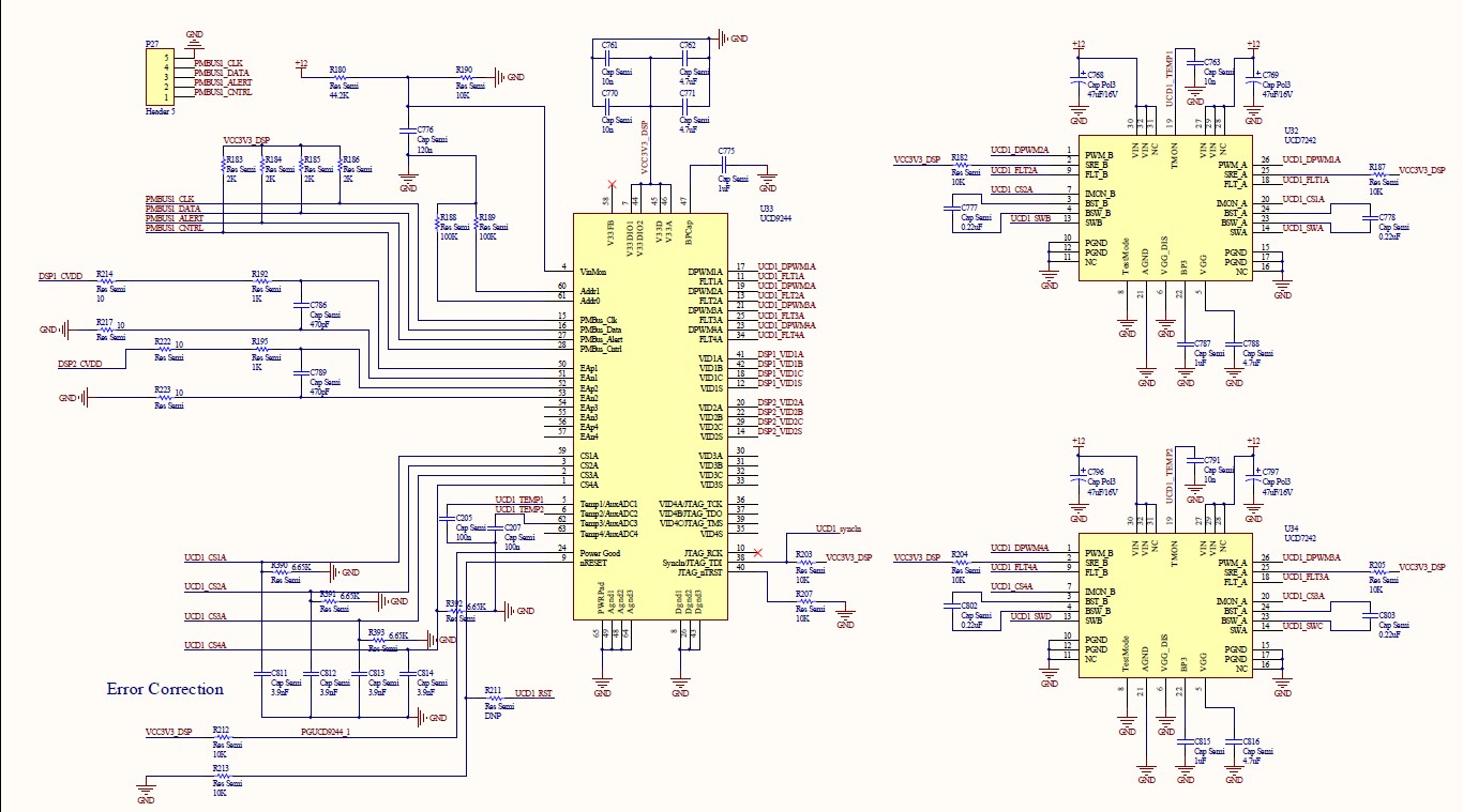
Setup is on the board where there are FPGAs or memories, just the power modulles, clock ICs and few other microcontrollers. We wanted to test the power controller and then start work on the board which has FPGA, memories etc., First, we programmed all the three controllers with power rails, limits, sequencing etc., We are able to see the outputs from the regulators (PTDxxx). Every time we modified some parameter we saved the project and wrote to hardware through the fusion software and adapter. After all modifications are made, we are doing "Send RAM to Flash" which writes all config data to controller flash memory. Ideally, after writing to the hardware and resetting/power cycling the board, the power modules should generate the voltages we had set. However, we are observing that all the powers are being turned-off and cannot see any outputs.

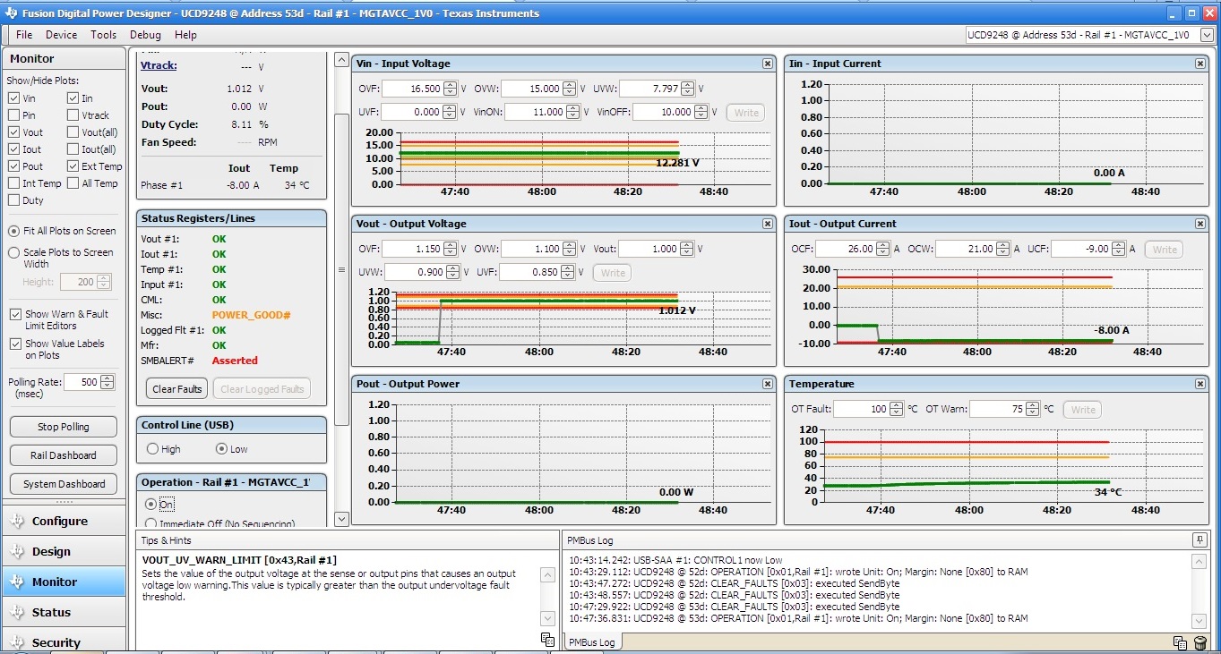
Also, when we use Monitor in Fusion SW, all power rails are off and if I set tun-on, then I can see the power rail turned-on. In status it says Power good# and SMBUSALERT# asserted. When I turn-on all rails manually, both power good# and SMBALERT# shows OK. Attaching a screenshot of monitor for your reference.

Is there any issue with the settings or the procedure which we are following? How to make the power rails stable after the reset/power cycled. One point we observed in the monitor was that the output current shows -8A, why is this due to? Is it because of no load?

Attaching the xml file for one of the module at address 52d. Please help us by providing suggestions.

Thanks,

Naveen

  • Naveen,

    Your configuration file has the ON/OFFCONFIG set for Operation command, this is a PMBus command that will need to be sent after each power up in order to turn the rails on.

    Setting the ON/OFF CONFIG to Always Converting will bring the rails up automatically when power is applied, the rails will follow any additional Turn On Dependencies or Turn On Delays that has been configured.

    Control Pin is also an option for ON/OFF CONFIG but you would need to have the PMBUS_CNTRL pin tied to the system to initiate the startup.

  • Brad,

    Thank you very much for your support. I could change the settings and got the UCD device working. Now our board is up and running. Thanks a lot.

    Naveen

  • Hi,Naveen HN,

      I was working on UCD9244+UCD7242 to powe supply for TMS320C6678, when i congiure my project ,I just saw o output and the duty cycle was always 0.Did you konw why? and I was just not sure if i must change the CVi, RVi1, RVi2, Cp, Rd1and L  in the "Edit Full Power Stage in Schematic "  so that these values match with my own Circu? wish you help ,thanks a lot.

  • Hi LBJ,

    There could be many reasons for NO output. Make sure that the schematics, assembled components are correct. Check whether the TI GPIO adapter is able to detect your UCD9244 device on board and able to program your UCD device with generated XML file. You can change the values of CVi, RVi1, RVi2, Cp, Rd1 and L according to your circuit. You can see the output power supply behavior in simulation for the values that you have changed. Looking into your problem, I think something is not enabled because of which you are not getting any output. You can share your xml and schematic screen so that they can be checked. Hope this helps.

    Naveen

  • Thank you very much ,Naveen!

        My USB adapter can detect the 9244 and my XML file can program into the device. And when i also change the CVi,RVi,Cp,etc. the output was still 0,the duty cycle was 0, so there must be something wrong whith my schematics or my XML file, attachment are my schematics  and XML file. I use one 9244 and two 7242 to provide 4rails with 1.1V core voltage, but now we just use rail1 and rail2, the rail3 and rail4 are not use by now. I appreciate your help,thanks again, in great need of your help. 4370.UCD9244_930_two_core_rails.xml

  • Hi LBJ,

    I am not an expert on these power controllers. I am providing these observations based on my previous work with UCD9248. Anyone from TI can correct the observation if not correct.

    1. The nRESET of UCD9244 is pulled down to GND. It is recommended in datasheet to pull-high with 10K resistor.

    2. Capacitor connected to BPCap must be 0.1uF where as it is 1uF, not sure whether this matters?

    3. VinMON resistor connected to +12V must be 56.9K or 57.6K.

    4. Are you using VID pins for controlling the output voltage? What are the values used for VID on board? As per the xml file, the VID is set to 6-bit mode. You can set it to 4-bit mode and set all VID1 inputs to HIGH so that you will set output to 1.103V. Also, you can check with "Ignore VID" option in VID tab and provide VOUT command through PMBus and check for output.

    5. If you are using all rails of UCD9244, rail 1 output must be connected to EAP1/EAN1, rail 2 to EAP2/EAN2, rail 3 to EAP3/EAN3 and rail 4 to EAP4/EAN4. Make sure all connections are proper including VID for all 4 rails.

    Please check the above and let us know your observations.

    Naveen

  • thanks,Naveen

      From my point,

      1.The EVM nRESET of UCD9244 also pulled down to GND,and the UCD9244 document's  Typical Application Schematic suggestion also show pulled down to GND.

     2. BPCap  can be 0.1uF~1uF(UCD9244 document page 18)

     3. I can't find VinMON must be 56.9K or 57.6K ,can you give me a link? 

    4. I did't use VID by now

    5. I did feedback the rail to EAP1/EAN1,etc.

    I dout if i miss someting or my XML file was wrong, could you tell me which part of the "fusion designer " should i Pay attention to?? many thanks to you

  • Hi LBJ,

    1. On nRESET signal, refer to UCD9244 datasheet, page 11 where it is shown that 10K pull-up is required. JTAG_nTRST is to be connected to GND through pull-down resistor. Remove the pull-down resistor connected, replace it with capacitor and use a pull-up resistor (10K). Think this should help to bring the device out of reset and see the output. You can follow the reference schematics in datasheet.

    3. VinMOD resistor is mentioned in reference schematics in Page 11 of datasheet and also it is one of the value generated in TI Fusion Designer tool.

    4. As per your xml setting, you have set it to 6-bit VID mode and not using VID, think these are floating in your case. If you see "Configure" tab section in TI Fusion designer, under "VoutConfig", on the right side there is a comment saying VOUT will be set by VID code. This means that if you don't use VID, you may not see the output. Could you please connect these to proper levels and check the outputs?

    Wanted to check how are you controlling the VID inputs to UCD9244 device? Better option is to set the VID to 4-bit mode (in "VID Config" tab) and pull-high all VID pins to VDD (3.3V) using 10K or 22K resistors for each VID line.

    Please check and let us know what happens.

    Naveen

  • thank you,Naveen

         the problem has solved ,thank you very much!

  • Hi LBJ,

    Good to hear that your problem is resolved. For our knowledge, could you please let us know what was the issue and how was it resolved. This would help others.

    Naveen

  •  wo just make sure the Capacitance next to the output rail are wrok well, because wo found that Capacitance was brokn down before,and the output feedback to EAP/EAN was wrong. wo just had the two problems, thanks.