This thread has been locked.

If you have a related question, please click the "Ask a related question" button in the top right corner. The newly created question will be automatically linked to this question.

BQ24192 charger IC for Li-Polymer- circuit design issue?

Other Parts Discussed in Thread: BQ24192, BQ24196

Dear TI team,

As for your suggestion we are choosing bq24192 charger IC for our 3.7V,20Ah Li Polymer battery,it will charging at 4.2V,4A. But we have some doubt in application circuit. Please advice for the following  queries.

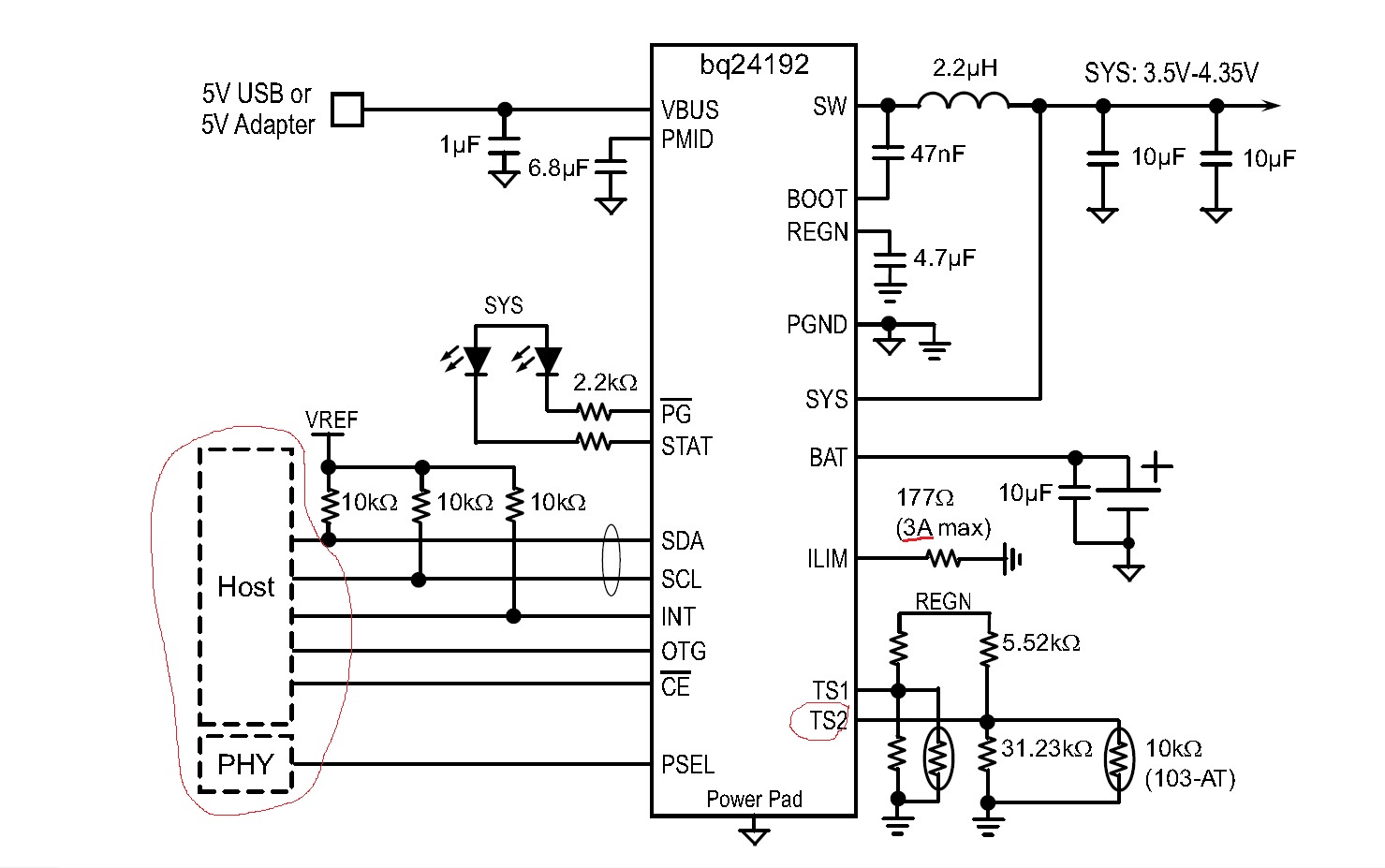
1. We don't use host  for register configuration,but we need to charge at 4.2V,4A. Is this possible to achieve? If yes, how to achieve? Advice.

2.Battery charging voltage is 4.2V or its adjustable. If adj how to fix it for 4.2V

3.In circuit there are 2 thermisters. What is the purpose of 2? Can we use only one thermister? How?

4.We need 4A charging current.What i have to do for getting 4A?

5.SYS voltage = BATTERY voltage or its proportional to each other? Please advice.

6.We have 5V,4A supply,But in circuit mentioned max 3A.Can we give 4A or i need to limits for 3A?

      Our device working well at 3.4 to 4.5V,1.2A . If any changes (components/values/any) required in this circuit please advice we need to design PCB and all.

We will appreciate your earliest response.

Best Regards,

Naveen K


  • Hello Naveen,

    1 & 2. The BQ24196 has its default battery regulation voltage set to 4.208V so it is possible to have your desired battery regulation voltage with out adjusting any of the I2C registers. However the charge current is not adjustable in hardware. You will need to use the I2C to modify REG02 to change the charge current from the default 2.048A to the desired 4A.

    3. The two TS pins allow you to monitor the temperature in two places in your system or provide redundancy. If you you only want to use one of the TS pins simply bias the unused pin into the safe operating range with a resistor divider. The temperature controlled operation of the BQ24196 is triggered when either one of the TS pins senses a fault so having one simply biased by resistors will not negatively impact the TS features.

    4. To achieve 4A charging you will need to size your power components accordingly to provide the desired output current and you will need to plan your layout to accommodate the high charge current.

    5. The relationship between the voltage on the SYS and BAT pins is explained well by Fig. 26 from Pg. 24 of the datasheet seen below.

    6. The input current limit is maxed at 3A but with a 5V supply providing 3A you could charge at 4A quite easily for the lower battery voltages. If you really need to charge at 4A you will need to raise your input source voltage to make sure you stay under the input current limit when the battery approaches 4.2V charging at 4A. Simply calculate the charging power requirement of about 16.8W with the charger efficiency @90% which would require a minimum of 18.67W on the input meaning to stay under the 3A input current limit you will need an input supply voltage of at least 6.23V.

  • Hello Ryan May,


    Thanks for your information and appreciate your support.


    Regards,

    Naveen K