This thread has been locked.

If you have a related question, please click the "Ask a related question" button in the top right corner. The newly created question will be automatically linked to this question.

Difference between the LM3478 and LM3488?

Other Parts Discussed in Thread: LM3478, LM3488, LM3481, LMV431, TPS40210

Hello,

We are having an issue in production with the LM3478 that we believe is the part reaching 100% duty cycle, and once it hits 100% it just shorts the input and it can't recover. That event can occurs pretty often especially if there is a low current limit at the input power supply.

We are looking for a drop in replacement.  I see that the LM3488 is pin for pin, but I can't tell what is different between the LM3478 and 88?  I don't know if it would solve our problem.

Thanks for your help

  • Hello Jamaal,

    The LM3478 and the LM3488 both have the capability to hit 100% duty cycle. Both the parts also do not have any Under Voltage Lock Out feature either. Therefore what happens is that with the input voltage rising, the part turns on at its minimum Vin threshold, which is 2.97V. Depending on what the output voltage is, there will be a large current draw from the input power supply. If the current was limited as you noticed on the power supply, the power supply would now be current controlled instead of voltage controlled. This situation leads to the output of the LM3478/88 to not reach regulation because of the lack of current from the input.

    Consequently internal to the part, the error signal will keep rising and at a point will not longer intersect the current sense signal. This would lead to the switch never to shut off and effectively hit 100% duty cycle. The easiest remedy would be to have a larger current limit at the input power supply so as to not starve the LM3478/88 output. But if this is not possible, there are two other ways somewhat simpler ways:

    1) You could introduce a zener diode between Vin pin and the supply. This will limit the minimum voltage to something above 3V. Assuming you put in a 10V zener (with cathode connected to the input supply) with a series resistor of 10ohms, then your minimum input voltage at which the part will start is 13V.

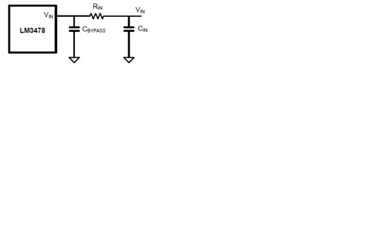
    2) You could also introduce a delay circuit which basically delays the switching. A resistor introduced from Vin pin to the input power supply along with a bypass cap already connected from Vin pin to ground would help generate a delay. The resistor value could be calculated as follows:
    R = tDelay/(C*ln(Vin/(Vin - Vinmin)))
    Where,
    tDelay = required delay time
    C = input bypass cap
    Vinmin = 3V for LM3478/88
    Vin = minimum vin of the required design 

    Another solution is to use the LM3481. The LM3481 does not allow a 100% duty cycle and has an extra pin with which you could configure the UVLO. I hope this information is helpful.

    Best Regards,
    Akshay 

  • Hi Akshay,

    I really appreciate your help.  Just to clarify, on suggestions #2.  You just mean a simple RC circuit like this, right?

  • That's right, Jamaal.

    Regards,
    Akshay 

  • Hi Akshay,

    We tried solution #1 with the zener, and it helps with the UVLO, however if we don’t use a large enough supply to run the circuit it can still have problems.  I am now playing with a combination of solution #1 and #2. 

    We have to work with a variety of loads, but even at 6A, this power supply cannot power up the product and blows the MOSFET, due to the large inrush current.

    We tried Webench for 1.5A a while back, although I can get away with 1A, and now can't reproduce the results.  The transformer in the older design becomes two distinct inductors.  I am thinking the Webench algorithm has changed?

    Anyway, looking at this section of the datasheet:

    SHORT-CIRCUIT PROTECTION (copied from the data sheet)

    When the voltage across the sense resistor measured on the ISEN pin exceeds 343 mV, short circuit current limit protection gets activated. A comparator inside the LM3478 reduces the switching frequency by a factor of 5 and maintains this condition until the short is removed. In normal operation the sensed current will trigger the power MOSFET to turn off. During the blanking interval the PWM comparator will not react to an over current so that this additional 343 mV current limit threshold is implemented to protect the device in a short circuit or severe overload condition.

     343mV / 0.016 ohm = 21A  Something does not make sense (0.016 ohm is from the Webench design)

     Would changing Rsense only adjust the current to a lower value?

    Thanks,

    Jamaal

  • Hello Jamaal,

    Would you please send me your design requirements? Also, please send me your existing schematic and board layout images/gerbers. Your design is a good candidate for the use of LM3481 where you have dedicated UVLO and a max duty cycle. The LM3481 also has a 4 times larger softstart time. The LM3478/88 has 4ms and the LM3481 has 15ms of typical softstart time. This will further help with reducing the large inrush current. Can your application take a board rework?

    The LM3478/88/81 employ the peak current mode control architecture. In this architecture, the inductor current is sensed and its slope information is used to generate the PWM signal. With every switching action, there is a leading edge spike which gets added on to the sensed inductor current. This spike is essentially noise and can lead to false tripping of the current limit. Therefore there is a blanking time incorporated to ignore this spike. But now, if this spike becomes very large then it could adversely affect the circuit operation. The 343mV limit is put in place to make sure that the part limits such large current spikes. 

    I am not sure what's going on with Webench, but we can get help from the engineers in that group if you can send us your design report and requirements.

    Best Regards,
    Akshay 

  • Hi Akshay,

    Any chance I could send this to you via email and not on the e2e?

    Thanks

  • Hello Jamaal,

    Please send those to simpleswitcherapps@ti.com

    Regards,
    Akshay 

  • Hello Jamaal and Eric,

    I received your Webench report and schematic in the email, but you did not send any layout gerbers or images. It would help to review those too.

    The main problem here is that there is a large input current requirement because of start up at low input voltages and less soft-start times. Unfortunately there are not many easy ways to mitigate this. If the use of LM3481 is not possible, then there is this additional circuit that can be used to extend the softstart time. I've attached the schematic that we believe will help. From the schematic, when power is applied at the input, the Css cap starts charging up at the current set by the Vbe of the BJT and the R2 resistor. If the R2 resistor value is set to 100k then, 

    Iss = Vbe/R2 = 0.7/100k = 7uA

    If the cap chosen is 10nF, then,

    tSS = Css*Vout/Iss = 10n*12/7u = 17ms

    Therefore this circuit will help you increase softstart to 17ms. This will help in reducing the inrush current and help reduce the load on the supply. You could even change the component values to increase the time further.

    I looked at your design further and saw that Rsns could be increased to 20mohms. The lower the Rsns value is set, the higher the current limit would be set. This current limit is essentially the FET current limit.

    Webench algorithm does look changed and I will ask them if they can somehow revert back. But as such, the design shared with me seems alright. I verified the component values and they should work fine.

    I hope this helps.

    Regards,
    Akshay

    LM3478_extended softstart.pdf
  • Hi Jamaal and Eric,

    Currently only uncoupled SEPIC designs are enabled for the LM3478/88 in WEBENCH. We are working to get the coupled designs re-enabled.

    Best regards,
    Tommy 

  • Hello Jamaal, Eric and Todd,

    The softstart circuit is just helping to reduce the inrush current. It would not help with the latch on of the FET at lower inputs. You really need UVLO for that. I have attached another small simple schematic which shows use of LMV431 for UVLO. Like I have said before, the best solution is still to use LM3481. I hope this helps.

    The upper resistor can be calculated to set the Vin min of the SEPIC circuit. The reference voltage of the LMV431 is 1.24V. 

    Regards,
    Akshay 

    LMV431 UVLO.pdf
  • Hello,

    I am resurrecting this old discussion since I am having the exact same problem with the LM3488. I made a SEPIC design using Webench, which latches at 100% duty cycle at startup. The zener UVLO method doesn't really help, it just delays the lockup until the input has reached a higher voltage. I haven't tried the RC-filter solution yet, but I suspect it will still be possible to trigger this fault condition in some situations. I also haven't looked into the more involved solution which modifies the circuit at the COMP pin.

    I am now considering a boost application instead of the SEPIC, and I assume it will also be susceptible to this lockup when using the LM3488. To me this seems like a fatal flaw in this component, since it's very common for power supplies to be current limited. I wish this had been more visible in the data sheet (the 100% duty cycle didn't catch my eye). I am curious to know when a 100% duty cycle is ever desirable, as it basically shorts the input, and I am surprised there is no built-in protection for this fault.

    Anyway, I am now looking at the TPS40210 as a possible replacement (I can source it cheaper than the LM3481 which you suggested). However, I can't find any mention of maximum duty cycle in the data sheet, so I don't know if it will be completely free of the issue discussed here. The configurable soft-start should be very useful.

    So.. does the TPS40210 have any risk of latching in 100% duty cycle, with a current limited input supply?