A related question is a question created from another question. When the related question is created, it will be automatically linked to the original question.
If you have a related question, please click the "Ask a related question" button in the top right corner. The newly created question will be automatically linked to this question.
In the figure, after power, VCC_1V_RESET_N goes high, enabling VCC_2.5V output, but VCC_2.5V_RESET_N has been low, resulting VCC3V3 no output, would like to ask why this is? Thank you!
I apologize for the delay. I am not sure I fully understand your question; however, I do notice that you do not have any pull-up resistors in the schematic. TPS3808 should have a pull-up resistor on the /RESET.
Thank you!The Tps3808(u44) /reset output is connected to the track of power module PTH08T240W and there is not a pull-up resistor on the /reset,but the /reset output work fine. so i think this is not the reason,thank you very much!
Thank you for restating your question. TPS3808 requires a pull-up resistor. Without using a pull-up resistor, you are not using the device as designed. There could be something on the U44 /RESET line satisfying the pull-up requirement that is not on the U48 /RESET line; however, to ensure proper operation, you need to add a pull-up resistor from 10k to 1M ohm as stated in the datasheet.
Thank you very much!Ryan.But I don't think this is the reason,I design my schematic follow the reference design "slva408",you can see it.1321.slva408.pdf
I'm not sure I would call SLVA408 a reference "design" as the drawing is clearly a block diagram and not a schematic.
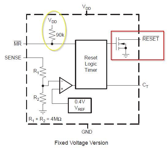
From the UCD3808 datasheet, the functional block diagram shows that the /RESET is an open drain output, red box.
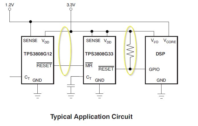
You will notice that the Typical Application Circuit from the datasheet, shown below, doesn't show a pull-up for one of the two devices. This is because it is driving the /MR of the second device which has an internal pull-up as seen above in yellow oval.
Having looked further at the PowerTrain modules and given that the same module is connected to both TPS devices and U44 works then either a TPS3808 with the wrong sense voltage is in location U48 or the power module isn't outputing a level high enough to reach the valid threshold of the TPS3808 sense input.
I have measured the power moudle output which is U48 sense input,it is 2.5v,the p-p ripple is about 120mv.At the same time I have checked the tps3808 chip mark and make sure it is tps3808g25.Thank you very much!