This thread has been locked.

If you have a related question, please click the "Ask a related question" button in the top right corner. The newly created question will be automatically linked to this question.

TPS61260 startup issues

Other Parts Discussed in Thread: TPS61260, TPS63030

Hello,

I seem to have a unique problem with the TPS61260 part. My application requires running off a CR2032 primary coin cell (3V). I have a TP63030 buck-boost down regulating the battery voltage to supply 2.4V to the board and the TPS61260 feeding off the 2.4V line to boost up to 2.8V to supply a NAND chip only when needed.

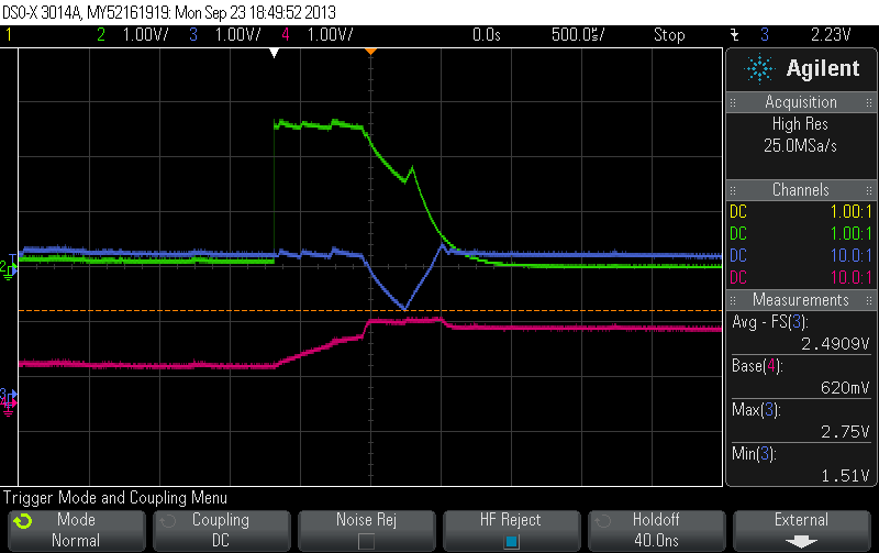
My problem is that on some boards, every minute or so when the NAND is enabled (the EN pin to the TPS61260 is taken from GND to HIGH) the output voltage starts ramping up and gets stuck at 1.5V, and quickly falls back down to 0. At this point, the 2.4V line has also dipped significantly (by 1V) causing the entire CPU to reset. I feel like it is drawing an excessive amount of current at startup that is causing the 2.4V line to droop.

I would like to get some of your suggestions on why this might be happening only on some enables and not all. I have sufficient capacitance on the 2.4V line (90uF +) and a 10uF cap right at the input of the TPS61260 as recommended in the datasheet.

Thanks,

Shriram

  • It is likely that the TPS61260 is drawing enough current during its startup that the voltage drop across the high internal impedance of your coin cell is causing the TPS63030 to hit its UVLO.  You can confirm this with a scope.

    I recommend increasing the Ri resistor on the TPS61260 to set its current just high enough to supply your NAND.  This resistor also sets the inrush current limit.  So, reducing the current limit would result in less inrush.

    It also might be a good idea to test the TPS61260 powered directly from the coin cell.  There will likely be enough losses across the internal impedance and inside the TPS61260 to operate with Vin near Vout, instead of Vin > Vout.  This would be a more efficient power supply.

  • Thanks for the prompt response, Chris- appreciate your feedback.

    I've attached a screenshot:

    In the image, the PINK is the 2.8V output line and the BLUE trace is the 2.4V buck-boost that feeds the TPS61260. The GREEN trace is a GPIO from the MSP that I set to toggle when the NAND write is enabled (regulator is turned on). As you can see, the 2.4V dips to around 1.5V but is still above UVLO per its datasheet.

    I'm curious as to why this doesn't happen all the time and on all boards if it has to do with startup inrush current. Could there be a component to component variability here?

    In the past, I've had startup issues with this part and talking to one of your FAEs, they recommended that I have a pull-down at the output to forcefully discharge the 2.8V node before re-enabling. They said TI was working on a silicon spin of this part to fix the issue. I was also able to resolve it using firmware by having the SPI "CS" signal enabled first so the 2.4V on that line backcharges and sets the 2.8V output to a 2.4V before enabling the regulator to get around this issue.

    Thoughts?

    Thanks,

    Shriram

  • To follow up from that previous post with a screenshot, what you see there is the 2.8V regulator failing to initially startup. The ramp on the PINK trace is the SPI back-charge I was referring to in the post (it pre-charges the node to 2.4V) where the boost regulator then kickstarts itself up to 2.8V.

    Unfortunately, this startup pulls a lot of current causing the 2.4V to drop to 1.5V which resets the processor.

  • You could order some TPS61260 samples from our sample room and test those.

    Since you have an FAE contact, he or she would be good to debug this issue with you.

    It does appear the you have 1.8V while having 2.4V in on the right of the waveform.  Normally, this would mean that the TPS61260 is in current limit and can't raise the output higher.  Could you check the output or inductor current for this possibility?

    The board to board variation might come from different batteries or even the same battery at a different state of charge.  1.5V is right at the UVLO level of the TPS63030, so I wouldn't be surprised if this waveform looked different on different boards of yours in case the Vin reached UVLO of some devices.

  • Thanks Chris.

    I didn't check to see if there was any current limiting on the TPS61260 kicking in, but I did repeat the tests powered off a bench power supply. I still see the same behavior consistently on the faulty boards. I don't see it on every board but so far, it's on about 3 out of 15. It looks like whether or not I use a battery, this issue happens.

    Do you know if there are any known startup issues with this part? The other hypothesis I had was to do with the voltage on the 2.8V line when the chip was enabled. Since the NAND accesses are not periodic, there are different intervals of time between consecutive enables to the TPS61260. Depending on the time between enables, the node discharges to a different voltage level. I've noticed that the part has startup issues when the node voltage is around 0.58-0.60V.

  • We addressed some complaints about the device almost a year ago now.  So, I recommend sampling new ICs from our sample room as these are the latest and greatest.

    If you still have startup issues and have isolated it to the ~0.6V pre-bias voltage, please contact your local FAE.

    It's still a good idea to check the current limit--if your load is drawing more current st startup, it sometimes looks like this type of behavior where Vout does not come up all the way.