This thread has been locked.

If you have a related question, please click the "Ask a related question" button in the top right corner. The newly created question will be automatically linked to this question.

Problem with TPS7A30xx and TPS7A49xx

Hello,

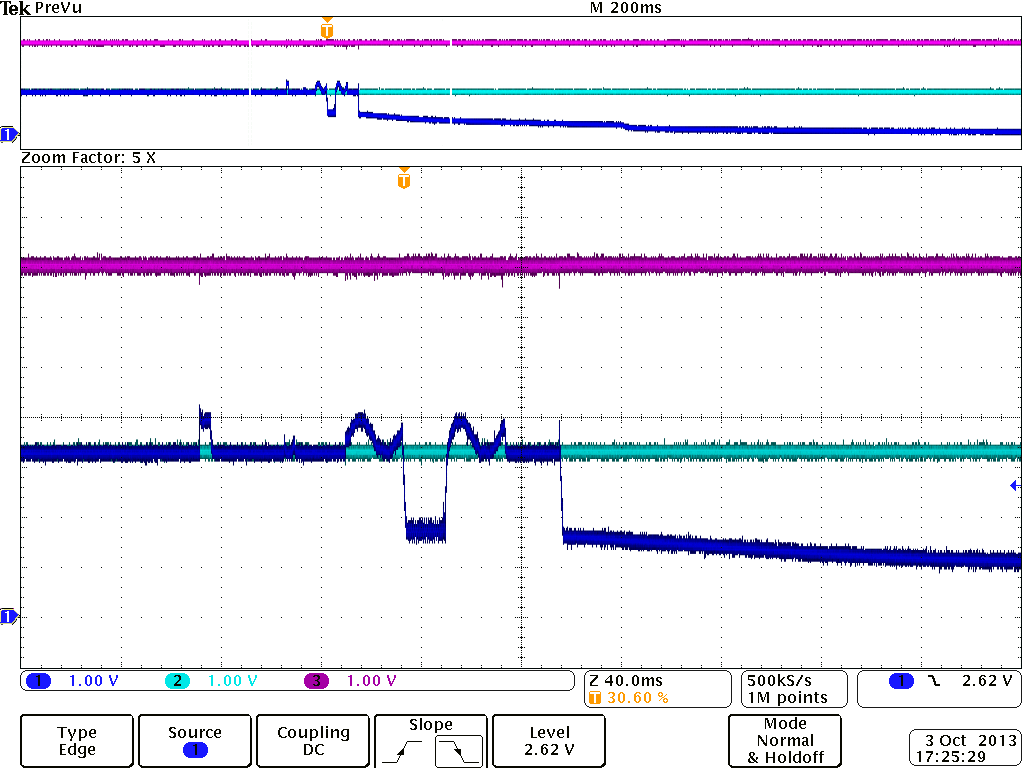
We may have e serious probem with the Do Not Connect pin (pin 7) of TPS7A30xx and TPS7A49xx - we left it unconnected as required but then if we touch it with finger the regulators stop working (output goes to 0). We started to investigate this problem because we have unexpected random drops of the power from these regulators in the fileld which leads to serious problems with the product - we have 5 of these regulators on a critical board of a 1MW solar converter which is under field test.

The suspect that root cause of the problems is charge pickup from these floating pins in the field leading to building such potentials that affect the circuitry inside and block the regulator operation.

I would liek to ask you for your as quick as possible reaction because the time is very critical - we need to solve the problem within the week. Is it possible that the problem we are having is related to the explanation above?

Thanks a lot in advance,

Radek 

  • Hi Radek,

    Would it be possible to share a schematic and waveforms of the fail condition?  This will help in debugging your application.

    Very Respectfully,

    Ryan

  • Hi Ryan,

    First let me thank you for your quick answer, we appreaciate it very much. Unfortunately I do not have waveforms at the moment, what we observed is was so far checked with a multimeter only. The reason to start investigating this was that at we saw our power supplies missing from time to time while the board was operating in the field. After board restart the supplies are restoring back. We took the board out and srarted to investigate in laboratory conditions - after power up the suppies behaved normally, then we start trying to stress them to provoke the failure and noticed that sometimes the failure is provoked by short circuiting the output, normally it would restore after the short circuit dissapeares but in 1 out of 10 times it will keep being low even after removing the short circuit. After power off/on it will restore in normal operation. We also noticed that the same thing would happen if we short circuit the soft start capacitor but the failure would happen more often - say 3 out of 10 times. Then the third experiment was to try touching the Do Not Connect pin with finger - kind of funny test - but the goal was to try impart some charge to the pin to see if charge build up there could lead to the fault - what we observed was that we were able to see the fault very often - 7 out of 10 times. The failures were observed with a multimeter and oscilloscope connected to the OUT pin but we don not have recorded waveforms at the moment.

    I am sending the schematic for the moment - hope this could give a starting point for you to debug. But in general it is really strange to have a pin that you must not connect - it would most probably be some test pin but then usually it is needed to connect this test pin to some fixed potential and not to be left floating - now we have a floating pin that is kind of suspicious - could you please explain if possible what is this pin for? 

    The schematic of 2 of the 5 power supplies is shown below - +10V and -10V, the rest o fthe supplies use the same schematic but with different resistor divider to have different voltatges - 1.8V, 3.3V and 5V:

    Thanks,

    Radek

    We also succeeded to record pictures of the fault - in this case it was reproduced by one time shorting the soft start pin NR/SS to GND and removing the short. The soft start capacitor in this case was removed, the supply is 3.3V one. The pictures below show OUT (dark blue), IN (pink), Enable (light blue) - the second picture is the same event but zoomed, even after removing the short the OUT is keeping low and restores only power on/off of the board. The ripples on the OUT voltage are caused by the manual short of the NR/SS pin to GND:

  • Hi Radek,

    Thank you for all of the information!  It certainly give me a better understanding of what you are doing.

    1. Shorting the output: My concern here is the amount of power going through the device here.  You could be causing an over temperature condition that is damaging the devices.
    2. Shorting NR/SS: As seen in the functional block diagram, this pin goes to the bandgap.  It is not recommended to short this pin as it is not designed to take much current.
    3. Finger probing: It is possible that you are causing an electrical connection unintentionally to another pin or voltage due to the small size of these devices.
    Do you know which of your experiments is more close to the field conditions?  I would expect the over-temperature condition to be the most likely in the field.  Have you looked at your heat sink?
    Very Respectfully,
    Ryan
  • Hi Ryan,

    Related to shorting the output we did it for a very short time (1s) which would not lead to over temperature triggering. There is also the internal current limitation which the chip survives for unlimited time so we could not have damaged it doing this. In the field the temperature on the board was not more than 60degC and we measure with thermal camera the chip temperaure rise of 40degC maximum relative to ambient so there is enough room till the over temperature shutdown (Tj=170degC) and also the maximum opretaing temperature 125degC so this does not seem to be the reason. Related to shorting the NR/SS pin you are rightthat does not sem to be very safe manipulation but it is done also for really very short time (1s) and sometimes the chip restores back to normal operation sometimes it does not. I would expect that the internal bandgap circuit buffer will go into its maximum output current - some uAs of current, could be calculated from Fig.23 of TPS7A49xx datasheet - 1.2V*10nF/10ms=1.2uA - I would say this small amout of current could not have damaged the chip even if there is constant short on the NR/SS pin to GND - only the regulator will output zero as long as this condition is present but need to restore back to normal operation after this condition disappears.

    About the finger tip probig you are right we could have touched other pins and most probably we have touched the NR/SS pin also - right next to DNC pin and then the fault provoking mechanism would reduce to the above one.

    About the fault mechanism in the field we are not able to say anything as we were nto able to see it consistently at the convereter in the field - boards are mounted in teh cabinet and it is not possibel to observe the operation closely with oscilloscope. Our observations were done in the lab where we tried to sterss the chip in controlled ways that we think would not damage it. Based on the behavior after shorting the NR/SS pin we tend to think that inteh field there are high EMC disturbances (kA switching at kV) and there is some part of the chip that latches the internal circvuitry to bring the output low, after power off/onn sequence it restores back. The behavior when shorting the NR/SS pin would in our opinion support this explanation. Also the presence of Do Not Connect pin which we do not know anything about - is it floating and prone to pick up charges or EMC disturbances for example is something that bothers us.

     If we would need to change the regulator could you please propose an equivalent pin-to-pin compatible one?

    Thanks a lot,

    Radek

  • Hi Radek,

    I have a couple of questions that can help with the debug of this as well as some comments:

    1. Are the drops you mentioned in your first post the same as what your seeing in the lab (where the part turns off and does not turn back on until you cycle the power)?
      1. If you leave Vin high does cycling Ven cause the part to return to normal operation?
    2. Are the temperatures you gave in your last post the temperatures in the field cabinet or in the lab?
    3. In the field is there someway for the NR/SS pin to be shorted to ground? The only thing that should be connected to this node is the noise reduction capacitor (which seems to be the case from your schematics). So I wouldn't think there is an easy way for this to be pulled low.
    4. To answer your question regarding the Do Not Connect Pin: during normal operation when the part is regulating normally the Do Not Connect Pin is a high impedance node. During startup or when the output is out of regulation this is a low impedance node to ground. 
  • Hi Kyle,

    Here are the answers to your questions in the same order:

    1. In the field the fault was manifesting itself in the same way as in the lab - the regulator turns off and comes back after cycling the power (or with cycling the Ven pin - see a. below), but what disturbance was causing the turn off in the field we are not able to say.

    a. If we cycle the Ven pin only without the cycling the power (Vin stays high) the regulator comes back into operation - this was a work around we tried to solve the problem but then it led to some other problems with the software so we needed to abandon it.

    2. The temperatures that I gave in the last post are the temperatures in the field, in the lab we tested at room temperatures.

    3. There is no circuitry on the board that could short the NR/SS pin to GND in the field - the only component connected to the pin is the noise reduction capacitor.

    4. Thanks for the explanation about the DNC pin - one additional question - since it is highZ when in normal operation could the chip be vulnarable to high EMC disturbances that could enter via this pin?

    Thanks,

    Radek

  • Hi Radek,

    We are attempting to replicate what you are seeing.  We will update you with our findings.

    Very Respectfully,

    Ryan