This thread has been locked.

If you have a related question, please click the "Ask a related question" button in the top right corner. The newly created question will be automatically linked to this question.

BQ3060 Error

Other Parts Discussed in Thread: BQ24745, BQ3060, BQ29412

Hi guys,

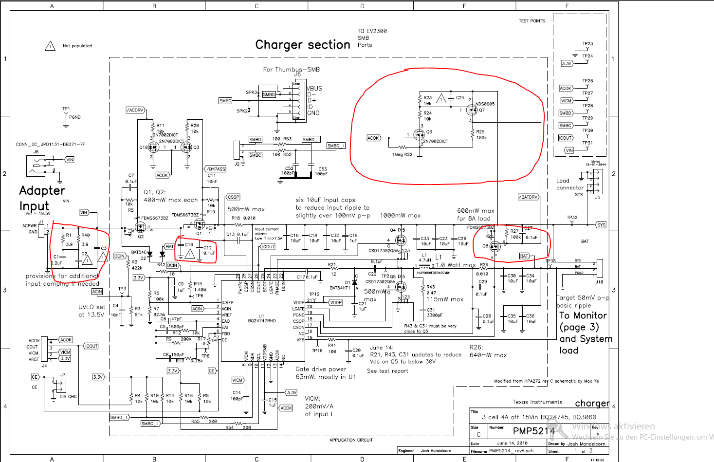
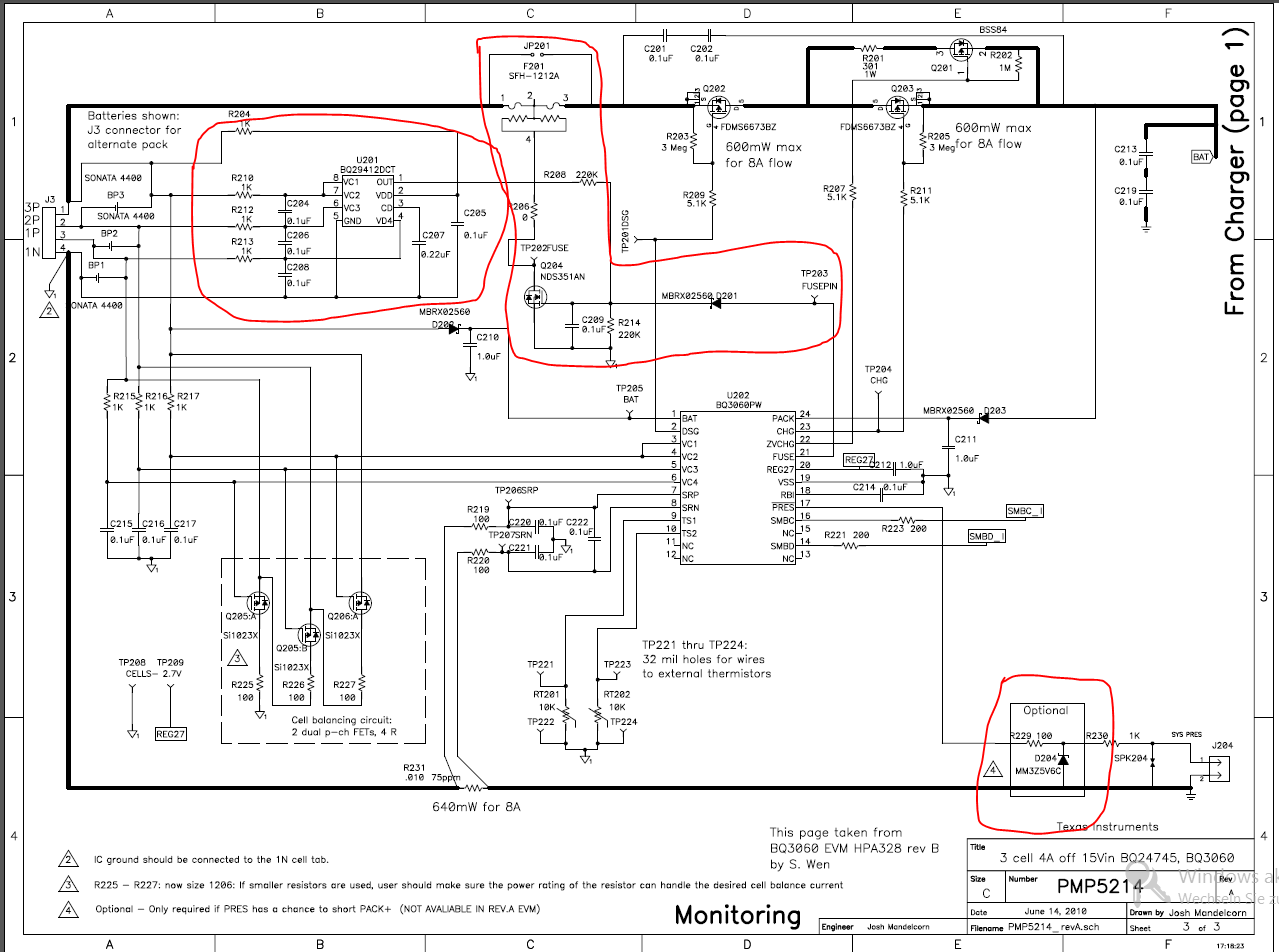
I do have a Problem with the BQ 3060 Gas Gauge. I designed almost the same circuit as on the reference design (http://www.ti.com/lit/ml/slur112/slur112.pdf) just left out the optional things (marked red in the attachment). Everything works fine so far but there is one issue that I can't solve: -->  when I remove the battery pack I can't turn on my device anymore

I did some measurements and have found out that:

when I plug in again the battery pack DSG is turned off so I can't use the battery to power my device

when I short BAT (PIN 1) and PACK (PIN 24) DSG is turn on and I can power up my device with the battery pack

also I can "activate" the BQ3060 when I start charge with the BQ24745

Have anyone an Idee ? What can I do to solve this Problem or is it maybe nassery to have voltage on BAT and PACK all the time ( what I don't thing).

Here  are same facts how my System works and it is configurated:

My Charger IC is the BQ 24745 with the same components as in the reference design (just left out the red marked I think that are features and not needed). As Balancer IC I use BQ 3060 with the same components as in the reference design but with out the optional things like FUSE (in my schematic this pin is on ground), second safety IC BQ29412 and PRES (it's on ground).

My Battery Pack consists of 2 Lithium Ionen battery in an row so the BQ 3060 Data Flash is configure like that.

Is there any setting that I have to set in the Data Flash of the BQ 3060 too?

  • It looks like you have removed the SYSPRES connection from the pack. Did you set the NR bit to 1 in the Pack Cfg B register to allow the device to ignore SYSPRES?

  • Hey Thomas,

    thanks for replying. If I understand you right you can set the BQ 3060 with NR in a mode where the battery is not removable. In my solution PRES (PIN 17) is fix on gnd on the pcb do I have to set NR to 1? I've tried it but it's the same affect everything works fine but when I remove the battery and insert it again I can't switch on my device because DSG is high but why is BQ 3060 doing it after it loose power?


    I also notice that when ich remove the battery just for 1 s and insert it again I can switch on my device without any problems it's seems to me like bq 3060 do have a power back up for a short time period?

    The only way I found to switch on my device again is to short BAT (PIN 1) and PACK (PIN 24). But why is it working then?

    I can't do it so when I am charging.

    An other interesting thing is that the operation cfg c register is by default 0x0040 in the Technical Reference (http://www.ti.com/lit/ug/sluu319/sluu319.pdf page 146) but when I compare it to the given explanation underneath it should be 0x0004. Is there a mistake?

    Can you please tell me what are the default setting for operation cfg a ,b and c registers and what I must configure for my system as I mention before I do have 2 lithium Ionen batteries in series. 

    Are there any setting I must set to avoid that DSG is off when power is removed from BQ 3060.

    Thank for your time. :-)

  • The DSG pin will disable, if the device goes into Shutdown or loses power. Are you actually removing the battery from the device?

    If the device does lose power or go into Shutdown, then you do have to apply voltage to the Pack+ pin to wake it up.

    The default values for the Operation Cfg registers are.

    Operation Cfg A: 0228

    Operation Cfg B: 0440

    Operation Cfg C: 0040

  • Hello Thomas,

    Yes I am removing the Battery from the device, because of that it is necessary that the BQ3060 Balancer switch on DSG automatically so I can power up my device.

    What is the defference between when I am set NR bit to 1 and left PRES floating or I left cfg B as default where NR is 0 and connect PRES to ground? What should I choose for my solution : I do have to cells in series which I need to be   remove individually.

     At the moment my solution is to short BAT & PACK together permanent and it works so far I can remove and insert the battery and can switch on my device after that also I can charge without problem, but there is one problem with the shutdown voltage (which i would like to use for protecting the battery from deep discharging) shutdown occur but because of BAT & PACK is short together it turn on again so it toggels on / off quickly.

    Is there a possibility that I can remove my battery and after that nevetheless to turn on my device ?

    Are there any other dangerous behaivour of BQ3060 if I connect PACK & BAT together. 

    Why is in the reference design (http://www.ti.com/lit/ml/slur112/slur112.pdf) BAT & PACK not connected together or is it only necessary for removable battery system.

    Best thanks for the help.

    I'm almost at goal :-)


  • Hey Thomas,

    can you please answere my questions above. Also I notice that the balance performance isn't that great there is a difference between Cell1 and Cell2 of ca. 100 - 150 mv is it normal? Can I change the accuracy of the balancer somewhere? What is the best perfomance of the BQ3060 how much mV is the deference then and on which it dependes?

    Big thanks  for support.

    Yours truly

    Haver

  • You will have to wake the device up, if you remove the batteries and temporarily connecting BAT to PACK+ will do this. It is not recommended to connect them together permanently, due to safety concerns. The device will not be able to turn the open the circuit as the FETs are bypassed. I have seen people place a push button switch in the circuit to allow the user to reset (wake-up) the circuit. Another option may be to connect the Pack pin on the device to the Bat side of the FETs instead of the Pack+ side. This will wake up the device when the cells are attached. This should work okay, if you are using primary cells. If you are using rechargeable cells, then the charger would not be able to wake-up the device in the event the cells were to be discharged into a shutdown condition.

  • As to your cell balancing question, 100 to 150mV of imbalance is a lot. the device only balances during charge, so make sure that you charge to device and allow the current to taper. It may also take more than one charge cycle to balance completely, especially if you have high capacity cells. 

  • Hey Thomas,

    thanks a lot for your solution. I have tried to connect the Pack Pin to Bat Pin in the side of the FETs (instead to PACK +) it's works but as you mention in the case when the two rechargable lithium ionen cells in series which I use are deeply discharged maybe up to  6 V or 5,5 V ( at the very latest 5,5 V I have to disconnect the pack because otherwise they are in deep discharge and are damaged) so I can't switch on my device and can't wake-up it with the bq24745 charger. Is it right that the pack pin of BQ3060 need min 5,2 V to wake up(http://www.ti.com/lit/ds/symlink/bq3060.pdf Page 3)? 

    How much current do BQ3060 need when it's in shutdown mode because my idea is to do it like that:

    Request via the smbus all the time the average Voltage

    if the Voltage is near 6 V I do force the BQ3060 go into the shutdown mode ( I think it is possible with the Shutdown(0x0010) command. I am right?) 

    so now the BQ3060 need max. 1µA  (http://www.ti.com/lit/ds/symlink/bq3060.pdf page 5. ?right?)from the battery that means that even when the user not charge the device 1 week or longer the Voltage would be above 5,2 V so the charger can wake up the bq3060 device and charge the battery again. What is the command for wake up the bq3060 device or is it on when there is a current from the charger.

    Is my Idea right ? Is there a better possibily to wake up the device even when it's dircharged deeper as 5,2 V.


    The solution which would be perfect for me is that I can remove my cells whenever I like even if they are discharged up to min 5,5 V ( 6V is also ok) and after attached them again into I can switch on my device or at least charge the battery.

    Do you have an Idea ? ( I can't / won't use a switch or something like that just for wake up the device)


    An other Question is: How should I connect the PRES Pin when I would like to know/monitoring the present of the cells so I can tell the user that the cells are not attachend or yes.

    Thanks for quick help!

    I looking forward to hear from you!

  • what do you mean by " allow the current to taper." Yes I know that BQ3060 only balances during charging in a passive way : How can I check wether the cells are really balancing just measure the power on/off process of the Q1 or Q2 MOSFETs (http://www.ti.com/lit/ug/sluu342/sluu342.pdf page 8) ? What is the normal range of the difference between two cells after charge is complete ? By the way the flag CB is set during charging so it means bq 3060 balancing. 

  • Hey Thomas,

    can you please answer my questions above that would be pushing my project so bad.

    Thanks for help!!!

  • Approximately 5.2V is required to be applied to the Pack+ pin to wake up the device from shutdown and you are correct that the quiescent current in shutdown should be less than 1uA.

    You can use the Shutdown command (0010) to force the device into shutdown, but you must apply voltage to Pack+ to exit shutdown.

    I am not sure how you would use the PRES pin to indicate that the cells are not connected. It is used to tell the device that the pack is not installed in the system, so that it can turn the FETs off for safety reasons.

    You should use the CC/CV charging method, so the the charging current will be at the maximum value until the pack voltage approaches the full charge voltage. The charging current will then start dropping. This is the taper current and the pack should continue the charge until the current drops below the taper current threshold.

    You can monitor Q1 and Q2 to see if balancing is occurring and the CB flag should urn on when balancing is in process. We typically see the cell voltage within a few millivolts of one another.