This thread has been locked.

If you have a related question, please click the "Ask a related question" button in the top right corner. The newly created question will be automatically linked to this question.

TPS2421-1 Start-Up Problem

Other Parts Discussed in Thread: TPS2421-1

I am using a TPS2421-1 hotswap in one of our designs. We have 16 boards that function correctly, and one that will work with some benchtop power supplies but not others. It does not work with power supplies that have a faster turn-on ramp. As expected, FLT pulses low before the onset of Vout turn-on. The FLT pin is pulled up to the Vin supply which ramps to 3.3V. When the FLT pin pulses low, Ct starts to charge. FLT recovers from the momentary low pulse when Vin exceeds the UVLO of 2.8V. Vout starts to ramp, but Ct hits the 1.4V limit, and the hotswap faults out. 

What is interesting to me, is that the slower input power supply doesn't have the same problem. The voltage at Ct continues to charge while the IC is in UVLO well above and beyond the 1.4V threshold. Soon after the FLT pin goes high, the Ct pin starts to decay, but the FLT pin isn't tripped. I am currently attibuting this to the assumption that the Schmitt trigger is not yet properly powered (though I would expect it to be as soon as Vin >1V).

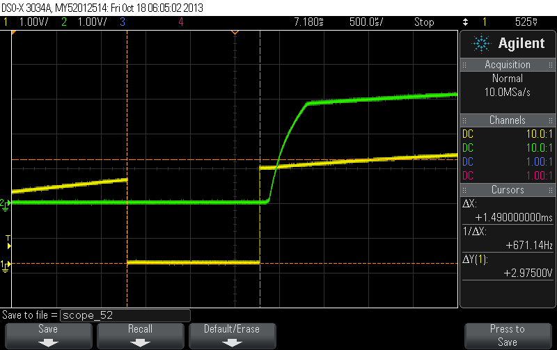
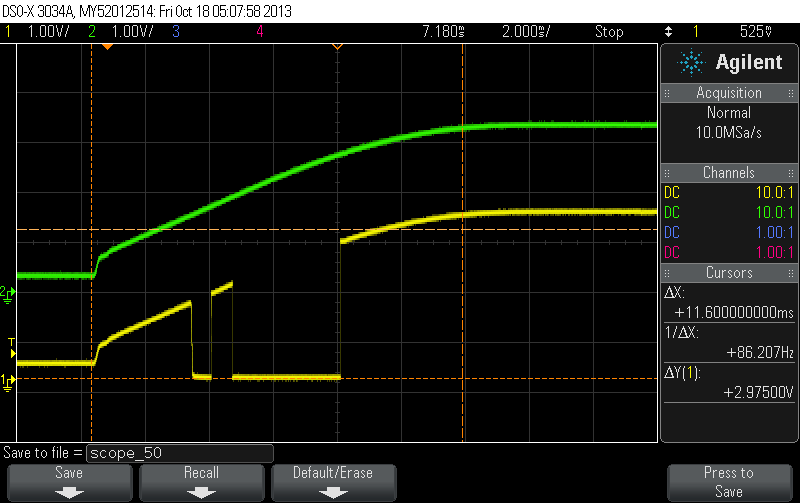
The other interesting nugget is the input voltage at which FLT pulses low (since FLT follows Vin via PU resistor unless actively pulled down), is higher one the board that doesn't work compared to the ones that do. FLT is pulled low on the "good" boards around 1.8V and stays low until the input voltage goes above 2.8V. On the "bad" board, FLT isn't pulled low until nearly 2.5V. Vin (green) and VFLT (yellow) are plotted for two different power supplies below. The first couple are on the "bad" board using the "fast" power supply, the next set is using the "slow" power supply, and the third is on a "good" board with the "fast" supply. 

Bad board, Power-On, Fast Supply. FLT pin goes low

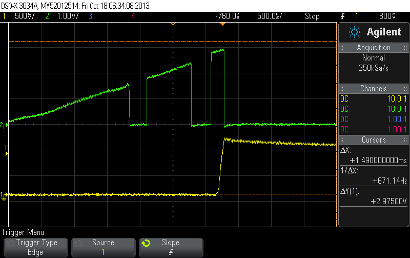
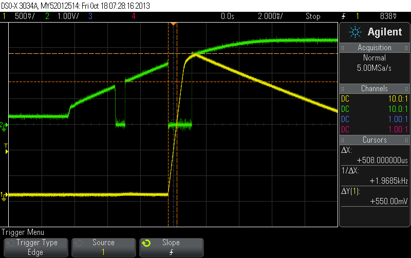
Bad board; Fast Supply: FLT pin (green) and CT pin (yellow). CT hits 1.4V and triggers FLT condition

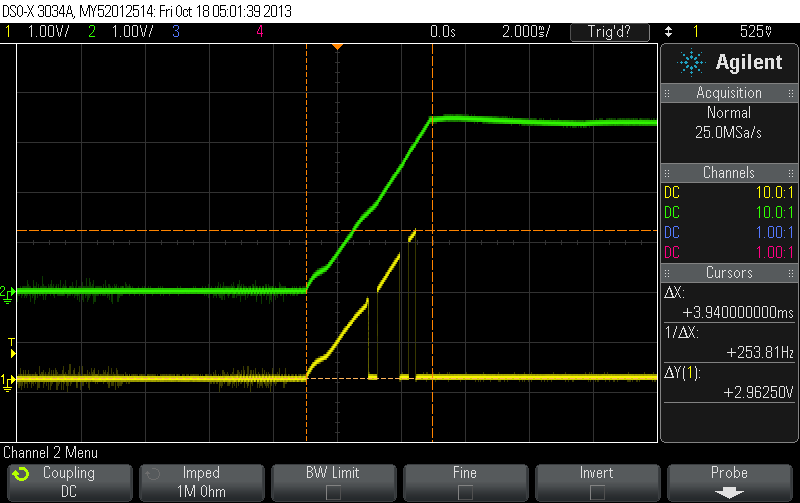
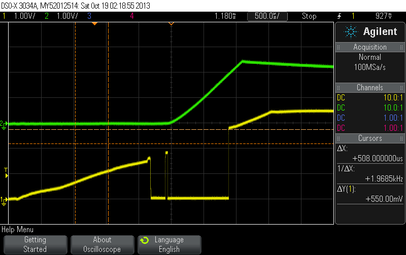
Slow Supply, Bad Board Power On. FLT pin doesn't go low

Slow Supply, Bad Board Power On. FLT(green)  pin doesn't go low, but CT (yellow) goes above and beyond 1.4V threshold

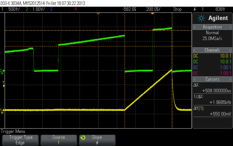
Good Board, Fast Supply, FLT(yellow) doesn't go low after Vout turn-on. Ct(green) goes above 1.4V, and FLT momentary low occurs aroun 1.8V

Increasing the capacitance on the CT pin to increase the fault timer appears to fix the problem on the "bad" board. I'm more interested in discovering the root cause and am interested in what controls the FLT pin to pulse low and at what voltage? All of the good boards have FLT pulse low around 1.8V, and the bad ones pulse low around 2.5V. Is this a defect or considered normal operation? What is the maximum, minimum, and typical input voltage at which FLT will pulse low?

Thank you for your time and consideration,

Carissa

  • Yes, this is indeed very strange behaviour. TI is aware of undeterministic behaviour of the FAULT pin during start up (FAULT will pulse low once or twice during IN based start up around UVLO and also if IN is already up and then ENb is taken low) and this is related to how an internal voltage rail is enabled/disabled. But your plots showing the CT pin charging above 1.4V is unexpected. We will have to set up an EVM and try to duplicate this behaviour and then get back to you.

    Do you have a scope plot showing FAULTb, ENb, CT, and OUT when CT exceeds 1.4V? We don't expect CT to start charging until OUT starts ramping up into the load. Is the output loaded during the above measurements?

  • Also, to clarify: the instances where CT exceeds 1.4V are the instances when the hotswap starts up properly, passes the expected voltage to Vout, and will shut-down after the fault time has passed if the load is exceeded. All behavior post initial start-up is as expected. Which leads me to assume that CT exceeding 1.4V during initial start-up might not be as un-characteristic as first expected. The instances where CT does not exceed 1.4V at start-up mean that the hotswap faults out and doesn't pass the input supply, so the rest of the board doesn't turn on. The main issue is that we don't want the sucess/failure of power-on sequencing to depend on the ramp rate of the input supply (at least within reason).  Any additional information you can provide regarding the undeterministic behavior during start-up would be appreciated.

    I've included additional plots of the signals you requested. I apologize that the plots are not all on one.  The output is loaded, but only minimally. The output serves as the input to some downstream LDOs with input capacitance in the tens of microFarads. The outputs of the LDOs are further loaded and the loads cannot be removed. Calculations indicate the load could be as high as .5A but we've measured nominal load closer ~100mA.  In all cases, CT starts charging before Vout starts ramping. Vout starts ramping when FLT# recovers from UVLO. EN# is tied to ground through a 0 ohm resistor. EN# was verified to be constantly pulled low during turn-on.

    "Bad" board, "slow" supply, FLT# (yellow)drops out and recovers around Vin = 2.8V. ~125us later, Vout (green) starts to ramp, ramps quickly while charging output caps then follows Vin. Note that this is the case when CT exceeds 1.4V (4th image in orignal post).


    "Bad" board, "fast" supply, FLT# (green)drops out and recovers around Vin = 2.8V. ~125us later, Vout (green) starts to ramp, ramps quickly while charging output caps, but faults out before it can stabilize. IC is latched off. Note that the FLT# goes low as a result of CT reaching 1.4V (2nd image in Orignal post).

  • To let you know, I've collected new information about this issue and am working to identify a suitable work-around. What is the value of the CT capacitor? The ramp up time seems a bit fast for most applications. FYI, there is a spreadsheet tool on the TPS2421-1 product page to help with the circuit calculations. You should be able to safely use a larger CT and reduce the susceptilbility to the VIN ramp rate.

  • Thank you; you're help and time at trying to find a work-around are appreciated! Changing the capacitance works for us in the short term, but doesn't give me the confidence I want for long-term production. The Ct capacitor is fairly low, only 0.012uF. I have already doubled the capacitance on this pin so that it will power up with both supplies, but don't feel that's the right solution without more information. If other TPS2421 parts pull the FLT# pin momentarily low at a lower input rail voltage, then even the increased capacitance won't be sufficient. Thus my curiosity for nominal, min, max values at which I might see FLT# drop-out. Given that, and a specific capacitor value, I would be able to specify an acceptable input supply ramp range. Otherwise, I'm just guessing  based on the FLT# cut-out voltages I've seen thus far.

    The second problem is that increasing CT reduces susceptibility for the faster supply, but increases it for the slower one. It also naturally increases the fault timer, which isn't the way we want to go for normal, post start-up operation.

  • Any word on the un-characteristic behavior? Anything else I can do to help find a root cause?

  • Carissa, we will contact you offline about this.