This thread has been locked.

If you have a related question, please click the "Ask a related question" button in the top right corner. The newly created question will be automatically linked to this question.

LM25037 isolated feedback

Other Parts Discussed in Thread: LM25037, TL431

Hello,

I'm currently designing a isolated power supply based on the LM25037 evaluation board (about 16...32V input voltage, and 5V/6A output voltage). But the evaluation board lacks an isolated feedback path. There is nearly no information in the LM25037data sheet how to implement it, and it is my first isolated power supply design. The only hint I found in the data sheet is to connect the feedback pin of the LM25037 to GND and connect the opto coupler to the COMP pin instead. This makes me somewhat curious ...

I've tried to implement the feedback according to the attached picture (Its some standard schematic from another isolated converter, and may need some fine tuning).

But with this approach, the output voltage is not regulated. It follows the input voltage. The output load (at Vout) is a simple 1K resistor (5mA at 5V output voltage).

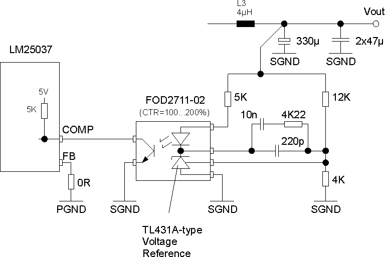
Can you give me some advice or comments to my feedback path implemention please ? Am I totally wrong with my implementation ?

Regards,

Martin.

-

  • Hi Martin,

    I would suggest a feed back circuit structure which has little differences with yours.

    http://www.ti.com/lit/ug/sluu429b/sluu429b.pdf

    To understand why the circuit does not work, monitoring the voltage on the middle point of 12K and 4k dividers would be the begining.

    It should be 2.5V if you are using TL431A . It is strange that the divider are 12k and 4k.

    Maybe you should check the adjustable reference you used.

    Another hint that the output follow the input, that usually means the converter is in open loop with the maximum duty cycle.

    Hope you can find out the reason with patience.

    Regards

    Kening

  • Hello Kening,

    Thank you for the info.

    The FOD2711 has a 1.24V reference included; The reference voltage is therefore not compatible with the TL431. That's why the voltage divider consists of a 12K and 4K resistor.

    But it seems that the output voltage depends not only on the voltage divider values, but also on the 5K LED Anode Resistor value. If I reduce it to approximately 3K, I'll get 5V output voltage. It is now stable within an input voltage range from 16V to 32V. I use an 1K load at the output (5mA load current) for testing. Looks good so far. I don't know why this Anode resistor has an impact on the output voltage though. The lower the anode resistor, the lower the output voltage. If this resistor is too high, I've got the open loop issue (no regulation at all).

    With the current configuration (4K/12K voltage divider + 3K anode resistor) I am able to deliver 5.0V output voltage at light loads. But when I increase the load current, the planar transformer generates audible noise. I can increase the load current up to 1.5A, while the output remains at about 4.8V. But there is heavy ripple (about 200mV) on the output. The higher the load, the higher the ripple frequency. The LM25037 is configured for current mode regulation.

    I'll check your suggested feedback circuit.

    Regards,

    Martin


  • Hi Martin,

    Are you using the synchronization rectification?

    If it is a diode rectification, then when the load is very light, the converter would work in DCM mode that means a very very small duty. 

    Regards

  • Hello Kening,

    I'm using two MBRD1045 Schottky diodes for rectification. In the reference design, a MBRB3030CTL is used.
    I will measure the duty cycle.

    But when I try to increase the load current to more than 1.5A, the regulator switches off, as if there is a overcurrent condition. We use a 27milliohm current sense resistor, therefore current limit should be much higher (about 9-10A).

    Perhaps I must adjust the RT2 resistor and check the Gate voltage of the switching transistors. The voltage on the sense resistor must also be checked.

    Thank you and best Regards,

    Martin.