This thread has been locked.

If you have a related question, please click the "Ask a related question" button in the top right corner. The newly created question will be automatically linked to this question.

bq24193RGET configuration

Other Parts Discussed in Thread: BQ24193

Hi,

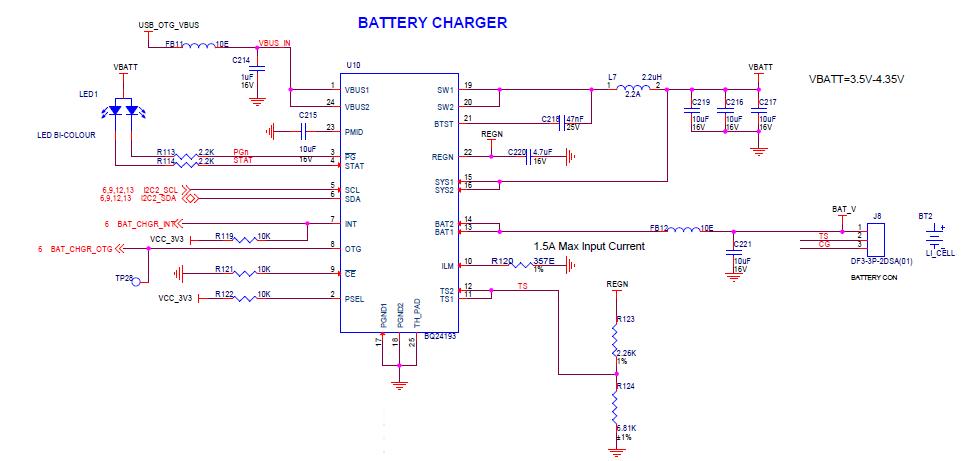
Does this charger works with and without battery plugged in i.e. battery less operation. In this battery less operation if the Vin is 5V or may be more, can we still have 3.5 to 4.3V to system. How much would be current supply to the system if Vin has more than 3A.

Ykfs

  • Hi,

    This charger can work without battery. We recommend to disable charge by pulling /CE pin high or configure i2c register to disable charge.

    It has a built-in DCDC buck converter which buck down the input voltage (3.9V-17V) to 3.5V-4.35V for SYS voltage. The maximum input current from Vin is 3A and the max I(SYS) supplies by the converter is 4.5A. 

  • Thanks. Sorry for the delayed response...i would like to know if battery is at 3.7V and may go down until 3.1V..in this case can we still have SYS output maintain at from 3.5 to 4.2 since other PMIC would have output from this SYS and has to be maintain at 3.7 to 4.2V.

    Ykfs

  • Typically the system load is connected to the system output and will not discharge the battery, unless the source is not available or the input power is limited by the source or the DPM loop. 

    The system output will track the battery voltage down to ~3.6V (battery at 3.5V) and then keep at 3.6v unless one overloads the converter.

  • Hi,

    We have used this battery charger in one more product. Attached is the sch. Sometimes we get proper VBATT = 3.6V and sometimes, VBATT goes to 2.9V which would make PMIC (which is powered from VBATT) failed to produce some of the voltages. Any specific reason why it has to go 2.9V from range is from 3.5 v onwards.

    INitially battery is not connected to the charger. Would it cause any serious issues.??

    YKFS

  • It looks like you have PSEL high, which implies USBinput, and not sure what OTG is biased to LOW (100mA) or HIGH (500mA).

    If your system load is too high you may be stuck in IDPM mode.  Check your input current versus your setting.

    What is your ILIM pin set to?  This could also limit the input current.  See data sheet for more details.

    The converter has short circuit mode if the system is below 2.2V and then the converter only delivers 100mA, but this does not seem to be your case.

  • Hi,

    Looking at the above schematics, can we have external power supply in place of battery. For ex. Instead of connecting battery can we connect bench power supply with 3.7V @ 1A to 1.5A rating. This case we would remove FB11 to isolate USB power (we would connect USB port to Host PC). Is this still ok.

    YKFS

  • The battery should be replaced with a 4 quadrant P/S that can source or sink current, so it can be used for charging and OTG.

    If you are just using OTG you should be able to use a lab supply.  Make sure you do not have too much inductance in your conntections.

    Please explain what you are trying to do and what mode when isolating the USB power.

  • Hi,

    Since we dont have such PS which can sink as well. We only have Bench power supply. The plan is the remove FB11 which will isolate OTG input supply to the Battery charger BQ24193. I.e. There wont be any input to battery charger. And Lab power supply with 3.7V@ 1A would be fed thru battery port connector.

    If this is ok then we can start our experiment.

    YKFS

  • Yes, that should work.

  • Hi,

    I have one more issues. When we plug in USB charger and read battery charging registers, it shows Battery discharging means battery is not getting charged. However, it detects power input to the battery charger.

    Any discrepancies in the attached sch please let us know.

    YKFS

  • Hi,

    Can you provide all the register dump especially REG08 & REG09? I don't think there is a "battery discharge" register bit, how do you get the information?


  • Is the power good pin low?  Is the BAT FET on....is the BAT pin voltage higher than the SYS pin voltage. 

    Make sure the TS pin is within range, if the power is good.

    Also when first powered the registers come up in the default values, so if the battery voltage is above the default value, then it won't charge.

  • Hi,

    We checked below things. Power good is Low. BAT FET is ON by reading register values. But one things observed, TS pin voltage were close to 3.7v and  when we changed R123 and R124 to 10K ( which was forming divider with approx 2v for TS pins, battery started charging. But with TS status as "overheat". There is no TS output for our battery. We have external Fuel gauge to sense battery parameters. 


    How get rid of this overheat while reading the battery charger registers. What could be the TS levels to be set.

    ykfs

  • Hi,

    Below is the log for battery charger.

    POWER_SUPPLY_NAME=bq24190-battery
    POWER_SUPPLY_STATUS=Charging
    POWER_SUPPLY_HEALTH=Overheat (when we change resistor divider value to 10K each)
    POWER_SUPPLY_ONLINE=1
    POWER_SUPPLY_TECHNOLOGY=Unknown
    POWER_SUPPLY_TEMP_ALERT_MAX=1200
    POWER_SUPPLY_SCOPE=System

    we want to know what could be the ideal voltage levels for TS pins if they are unused.

    YKFS

  • If the TS feature is unused, the pin should be biased at ~50% of REGN voltage.  From the datasheet you are correct to use two 10k resistors:

    Please measure REGN Voltage (should be 6V) and your TS pin voltage. The datasheet also provides the reference thresholds for TS pin functions:

    Please let me know if this helps or if you have any further questions!


    Best Regards,

    Rachel