


Other Parts Discussed in Thread: UCC28700, UCC28710
Recently,I used a chip LT3799 (PSR-CC with PFC) (http://www.linear.com.cn/search/search.php?q=LT3799)
,to design a flyback AC-DC converter. We know that for constant current control Iout=0.5*Ipk*Nps*Tdis/ T .
If the chip make the Tdis/ T constant, Then the output current is "constant". But I still can't understand how LT3799 make the Tdis/T constant (maybe not constant,but a |sin(wt)| )
How dose the A5 (integrator) work ? What the waveform will be like at COMP-,COMP+ ? How dose it calculate the output current with A5,A6,A7 and the multiplier ?
I really need help!
For convenience ,Now I paste the block diagram of LT3799 and some explains from the datasheet as bellow.
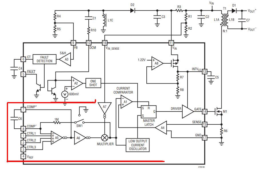
In the daasheet of lt3799, it says"
The CTRL1/CTRL2/CTRL3 pins control the output current of the flyback controller. To simplify the loop, assume the VIN_SENSE pin is held at a constant voltage above 1V, eliminating the multiplier from the control loop. The error amplifier, A5, is configured as an integrator with the external capacitor, C6. The COMP+ node voltage is converted to a current into the multiplier with the V/I converter, A6. Since A7’s output is constant, the output of the multiplier is proportional to A6 and can be ignored. The output of the multiplier controls the peak current with its connection to the current comparator, A1. The output of the multiplier is also connected to the transmission gate, SW1. The transmission gate, SW1, turns on when the secondary current flows to the output capacitor. This is called the flyback period (when the output diode D1 is on). The current through the 1M resistor gets integrated by A5. The lowest CTRL input is equal to the negative input of A5 in steady state. "
"The LT3799 has access to both the primary winding current, the input to the current comparator, and when the flyback time starts and ends. Now the output current can be calculated by averaging a PWM waveform with the height of the current limit and the duty cycle of the flyback time over the entire cycle. In the feedback loop previously described, the input to the integrator is such a waveform. The integrator adjusts the peak current until the calculated output current equals the control voltage. If the calculated output current is low compared to the control pin, the error amplifier increases the voltage on the COMP+ node, thus increasing the current comparator input."

