This thread has been locked.

If you have a related question, please click the "Ask a related question" button in the top right corner. The newly created question will be automatically linked to this question.

TPS54525 recovery from brown-out

Other Parts Discussed in Thread: TPS54525, TPS54526

Greetings,

I am having a brown-out recovery problem with the TPS54525 on the evaluation board (originally brought to my attention from prototype units, but duplicated the problem on the TPS54525 evaluation board).

The evaluation board has been altered to increase the output voltage to 5V (R1 -->124k, R2 -->22.1k).  VIN=12VDC (bench supply), Vout=5V, load is a 250R power resistor.

When VIN is ramped down to ~3.5V, then ramped back to 12VDC, the output stays low (pulsing, ~230mVRMS).  Has anyone else had this issue, or have any insights on this?

Scope captures: CH1 VIN, CH2 Vout, CH3 varies [EDIT: these captures are from the prototype board, not eh Eval board]

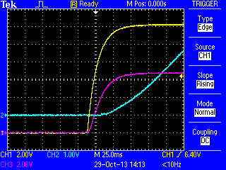
   Cold start (from everything off), CH3 Enable

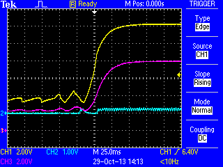
    Return from brownout, CH3 Enable

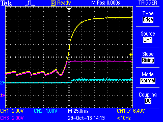
    Return from brownout, CH3 Soft-start

    Return from brownout, CH3 VREG5

  • Further reading and investigation within similar products (e.g. similar issue with TPS54526 reported) indicates that this may be an expected behavior: when a brownout occurs, a voltage sag at the output triggers UVP.  The UVP is a latching state.  Unfortunately, nothing else reaches a low enough voltage to restart the TPS54525 once an acceptable voltage returns: if I manually disable then enable using the jumper on the Eval board, the system is restored.

    Do you agree/disagree with this analysis?  Thoughts on a way to address this behavior?

    [EDIT: Capture from the Eval board]

     CH1 VIN, CH2 Vout, CH3 En, CH4 SS

  • I will look at this closer later this evening and get back to you.

  • Solution is below.  This has been tested with the Eval board and found to work.

    When the input voltage (+24V here, but varies by application) is below the zener breakdown threshold, no current flows through the 1k resistor.  This means that there is no voltage drop across the resistor, creating no voltage drop between the transistor base and emitter.  The transistor stays off, and EN stays pulled low.  Once the input voltage is greater than the the zener breakdown, the zener diode starts conducting.  The current through the 1k resistor creates a voltage drop.  Once the drop across the resistor is greater than VEB,ON for the transistor, the transistor turns on, pulling the EN line to ~VIN (less the transistor VEC saturation voltage).  If VIN goes below the zener breakdown, the transistor turns off, cycling EN low again.

    Set your zener voltage to 5.6V - you could use a lower voltage zener, but it cannot be less than 3.6V, which is the point that VREG5 would trip the UVLO.  5.6V has the advantage of being above the chip's operating range, and having a bit of inherent temperature stability due to the nature of a 5.6V zener diode.

    The transistor can be any small switching PNP (or P-channel MOSFET) that fits your application.

    [EDIT: Voltage in should be 12V, not 24V - 24V is outside of the operating range of the TPS54525.]

    [EDIT: Note that this is a general solution - your sensitivity, response, and voltage, current, and power requirements will no doubt vary]

    An additional note: I am disappointed in TI's John Tucker for acknowledging the issue, offering to address it, then letting it languish.