Because of the Thanksgiving holiday in the U.S., TI E2E™ design support forum responses may be delayed from November 25 through December 2. Thank you for your patience.

This thread has been locked.

If you have a related question, please click the "Ask a related question" button in the top right corner. The newly created question will be automatically linked to this question.

TPS62067DSG spike

Other Parts Discussed in Thread: TPS62090, TPS62085

 Hi,

  I am using a tps62067dsg switcher to supply +1.5 volts for a DDR3 ram circuit. While evaluating I noticed

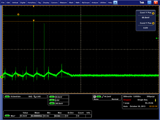
a random current spike occuring in the inductor. I am measuring the inductor (1uH) current by placing a 0.1

ohm resistor in series and reading the differential voltage on the oscilloscope with a 3.5 GHZ differential probe. My

load current is about 100mA. The inductor is rated at 4 amps saturation and appears to be acting linearly. The spike

is at the bottom of the ramp or the start of the ramp. What could cause this spike. I have attached a scope shot.

Thanks!


  • Hi Larry,

    I've never seen engineers have success with this method of measuring the inductor current.  You really should invest in a current probe to look at the current.

    As you correctly deduced, your inductor is rated appropriately and is therefore linear in this region.  Therefore, it is physically impossible for the current in the inductor to change that fast.

    This noise must be being picked up by your probe, which is measuring voltage and not current.  Voltage can change that fast and when it does, it radiates that signal through the air and into your probe.  Your probe is simply picking up the noise produced during the switching transitions of the IC.

    Since you are powering DDR memory, I would recommend using a DCS-Control topology device, such as the TPS62090 or TPS62085.  These devices can support much larger output caps and have much better transient response.

  • Hi Chris,

          I do have a current probe but I would have to make a large loop area (more parastitics) to capture the conductor into its jaws. I will try that next. The loop area on the diff probe and 0.1 ohm resistor is very small . I will let you know what I see. I the spike is of a nanosecond duration and looks like a pulse.

    Thanks!

    Larry

  • Hi Chris,

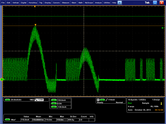
           Pictures look much better on the current probe!

    Thanks!

  • Yep :)

    As long as you keep the switching end of the inductor soldered to the SW pin and put the wire loop on the DC side (Vout), the extra parasitics and noise are kept reasonable.