This thread has been locked.

If you have a related question, please click the "Ask a related question" button in the top right corner. The newly created question will be automatically linked to this question.

UCC28950 / prevent DC magnetism

Guru 29720 points
Other Parts Discussed in Thread: UCC28950

Hi,

I'm sorry to ask about basic question.

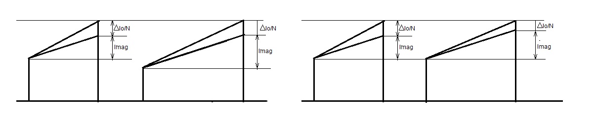
I think coupling capacitor in series to transformer is necessary to prevent uneven magnetism in normal full bridge configuration.

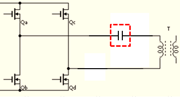
Is this capacitor unnecessary in phase shift full bridge configuration(UCC28950)?

Regards,

Yaita

  • You do not need a capacitor with a phase shifted full bridge controller such as the UCC28950.

    This is because the UCC28950 has an input monitoring the primary side current in the bridge. If the current looks to be unbalanced, then the controller will make adjustments to bring the current back into balance.

    Regards,

    John

  • But the op. amp. of the controller can go into saturation in the following cases and then I understand that there is no pulse by pulse current control. Then if the controller is too low, the transformer can go into saturation:

    - if the input voltage is too low: the output of the amplifier (COMP) saturates to the positive and the current control is lost. 

    - if you use a variable output voltage, using a variable reference voltage in EA+. A sudden change in this reference voltage causes the op. amp. to go to the positive, losing for a certain time the current control.

    - A sudden change in the load.

    The first problem can be solved  using a low voltage comparator that shuts down the control.

    The second, with a ramp in the control voltage.

    But for the last case a capacitor in series with the primary seems to be a solution and in the other ones, its safer.

  • Hi Franscesc

    Normally the PWM comparator terminates the present switching cycle when the peak current reaches the current demand point set by the EA inputs. This feature is present on both transformer polarities (OUTA/OUTC and OUTB/OUTD) and will prevent any DC flux in the transformer.

    If the EA saturates positive (it can go to 4.25V) - ie is demanding a very large current - then the cycle by cycle comparator acts to terminate the present cycle. Actually, the cycle-by-cycle comparator is always active and monitoring the output of the Ramp Summing block - effectively the CS signal plus the slope compensation inputs.


    In Current Mode control, this means that there is no possibility to have an imbalance in the transformer currents, ie no possibility to have a nett DC flux in the transformer core. The capacitor in series with the primary is not necessary.

    If the UCC28950 is used in voltage mode control the cycle by cycle comparator provides current limiting. I am unsure if the controller will protect against DC flux in the transformer when used in voltage mode - I'll check and re-post

    Regards
    Colin
  • Thank you very much for your reply, but I still do not understand why  there is no DC problem when the EA saturates. I still think that there are cases were this can happen.

    Take a real example, a converter in which I am working. Primary max. peak current is 6,5A, corresponding to 1,62 V in CS. The transformer starts to saturate at 1,2 A, that is 0,3 V in CS.

    Imagine there is a low input voltage, so EA saturates to +4,25 V, and 10% load, so primary peak current gives only 0,16 V in CS. The PWM comparator does not work because of the EA saturation, but the cycle by cycle current limit is active.  It will work, I think at 2V – slope comp. = 1,8V in CS. This means that it limits to 7,3 A the primary current. As 0,65 A is the peak primary current due to the load, the remaining 6,65A correspond to the DC component. So the transformer would be completely saturated.


  • The controller will not protect against DC flux in the transformer when used in voltage mode. This is because, in voltage mode control the EA output controls the duty cycle directly  – small differences in propagation delays etc etc will unbalance the duty cycle seen by the transformer. The result will be a nett dc flux in the core. Transformers are not usually able to deal with this DC flux and will saturate. It is for this reason that a DC blocking capacitor at the input is required. The cycle by cycle comparator does provide current limiting at the ILIM point, but of course the currents in normal operation will not reach the ILIM point.

    Now: taking your example, if I understand it correctly.

    Let's say that the input voltage is normal and you are at 10% load. The EA will demand a current of 10% of full load from the current loop. The EA output (COMP) will take up a voltage such that the PWM COMP trips at the correct level to deliver the demanded current.

    The input signal at the CS pin must be scaled correctly for the power train which the UCC28950 (or indeed any other device) is controlling. This means that the scaling has to be such that the transformer does not saturate when the signal at the CS pin reaches the level where the Cycle-by-Cycle current limit comparator becomes active.

    In your case, if the transformer saturates at a peak current of 1.2A then the current sense signal has to get to the ILIM level at a peak current of 1.1A (I've added some margin here).

    You may need to increase the amplitude of your CS signal. You will need to get a 1.8V signal at CS with 1.1A peak in the transformer. Of course if the CS signal scaling is wrong and the controller ILIM setpoint is greater than the level at which the transformer saturates - then you lose the protection provided by current mode control - I would not advise that.

    I hope this is clear

    Below is a markup of your last paragraph

    Imagine there is a low input voltage, so EA saturates to +4,25 V, and 10% load, so primary peak current gives only 0,16 V in CS. The PWM comparator does not work because of the EA saturation, but the cycle by cycle current limit is active.  It will work, I think at 2V – slope comp. = 1,8V in CS. This means that it limits to 7,3 A the primary current. As 0,65 A is the peak primary current due to the load, the remaining 6,65A correspond to the DC component. So the transformer would be completely saturated. True - bu the reason is that the CS scaling is incorrect and does not limit the current to 'safe' levels.


    Regards
    Colin

  • Hello Kensuke-San

    In answer to your original question.

    If the UCC28950 is operating in Current Mode control then a capacitor is not necessary. If it is operated in Voltage Mode control then a capacitor is necessary. This distinction applies to all devices controlling a full bridge power stage, not just the UCC28950.

    Regards
    Colin
  • In my converter the CT is well scaled. The peak primary current is 6,5 A and corresponds to 1,8 V in the CS pin, leaving 0.2 V for slope compensation. From this 1.8 V , only about 0.3 V correspond to the magnetizing current and the converter works fine in normal operation. If in abnmormal operation the EA saturates, the operation looks as voltage mode control, the cycle by cycle current limit does not work any more and only the current limit will limit  possible disaster, just as you say:

    The cycle by cycle comparator does provide current limiting at the ILIM point, but of course the currents in normal operation will not reach the ILIM point.

    If the ILIM point is reached at 2 V, and the cause is the DC in the primary, then the transformer is completely saturated.

    You may try this: Take the Evaluation Module, supply it with a low voltage, for example 200 V DC so the EA saturates as the 12 V output cannot be reached. Connect a low load and see (or imagine) what happens. 

    I mean that I agree that the capacitor is not needed in NORMAL operation, but if for some reason the EA saturates, it seems to be necessary.

  • Hello Francesc

    I took a UCC28950 EVM - ran it at 200Vin and 200mA load, Vout was about 8V at this point. I also tried it from 0Vin up to about 300V. There is no evidence of transformer saturation.

    Yel:  Transformer primary, pin 1 to pin 5
    Red: COMP pin on controller
    Blu: Primary current sense signal

    Vin = 200Vdc, Iout approx. 200mA

    EA has saturated, COMP is > 4V and the system is locked at max duty cycle –
    There is a small imbalance in the bridge on times - about 40ns. This can be seen in the peak current amplitude too.
    Ton:
    5.31 us on –ve part of waveform
    5.27 us on +ve part of waveform

    Regards

    Colin

  • Thank you for doing the test.
    40 ns over 10 us means 0,8 V over 200V.
    In the EVM the MOSFETs Ron is 0,22 ohm and the primary resistance 0,215 ohm. So I estimate a DC current of 1,2 A.
    I do not know the transformer characteristics so I am not able to calculate if this will saturate the transformer. It would not saturate the transformer I am using in my latest design (which supplies more than twice the power of the EVM), and probably does not saturate the transformer of the EVM.
    But in my case, Ron is 90 mohm, primary resistance is 28 mohm and I would get 3,8 A and 1,2 Teslas, so complete saturation.
    I suppose my calculations are right.
  • Hello Francesc
    I'll continue to think about this - I have some other work to do with this EVM and will try to include a look at this. I'll post when I have something interesting.
    Colin
  • Dear Friends,
    Good challenge on DC magnetizing current
    I faced the same problem:
    1- I think the pulse by pulse current control does not control the unbalanced current on the AD & CB legs, it only controls the current peak.
    2- Balance in current during two cycles completely results when both legs are designed balanced physically. and the most important part is the gate drives and leakage inductance on the secondaries of transformer (in current doubler design).
    3- an airgap in transformer can prevent saturation because it increases the saturation current
  • I do not agree. The peak flux is propotional to the peak current so if the peak current in each leg is the same, the peak flux is also the same. While the peak current control works, there is no possibility of transformer saturation.

    The level of peak current is set by the error amplifier. The problem is that if the error amplifier saturates, then there is no more peak current control. One cause of EA saturation is a too low input voltage. Or a command trying to get a too high output voltage. Or a sudden loss of load.

    In this case an air gap mitigates the problem, but does not solve it completely, and increases the primary current. The best and classical solution is a capacitor in series with the primary. If the capacitor is correctly sized, its voltage is very small, and the capacitor size is very small too. You may use SMD cermic capacitors. Just take care of the RMS current in the capacitor, do not surpase 20ºC of temparature increase. Normally several capacitors in parallel are needed.

    An important think to be aware, if you use low voltage ceramic capacitors, is that when the inverter is stopped the different current leakage in the MOSFETs may cause a too high voltage in the capacitor. The solution is simply a high value resistor in parallel with the capacitor. Do not forget it!

    Top give you an idea, in a 1400W converter supplied at 230V a. c. I use 4  x 2,2 uF  X7R size 1210 caps. The voltage in the capacitors is less than 5 V p.p. The resitor in parallel is 100 K. 

  • Thiking again on what Ali said, I have to agree partially with him, that in certain cases the peak current control does not prevent DC unbalance in the transformer.

    If there are different delays in the gate drives, or different Ron in the MOSFETs, this is not a problem, it will be corrected by the peak current control.

    But as the peak current control measures the total primary current, but not the magnetizing current,  I can think of at least two cases where a problem may exist.

    In the enclosed diagram,  the first drawing is a very improbable case of a split secondary which is not well balanced. The current reflected to the primary is different in each half cycle. The slope of the magnetizing current is always the same, V/Lp, so the peak limit is reached at different times and the magentizinbg current is not the same.

    The second diagram corresponds to a current doubler, where the two inductors have not the same value. Because the ripple current in each inductor will be different, the reflected inductor currents in the primary will be also different in each half cycle, and as seen in the figure, the magnetizing current is unbalanced.

    The drawings are exaggerated, but I think one has to calculate the unbalance of the magnetizinc current taking into acount the worst cases. Normally the DC current caused by the problems I have explained should be ver low and in the worst case just a small air gap will solve the problem, as Ali said. But the worst case is when the error amplifier saturates and then I think that the best solution is a capacitor in series.