I looking for comments/suggestions/corrections to the follow approach:
I have a battery backup application where the TPS2410 turns on the BBU ORing FETs when the system power supplies may drop power due to an input outage (ie, we want to switch on when an EPOW signal is received) as the application wants to ride through a short AC outage where the PSU may or may not drop out of regulation.
We have the battery dc/c output voltage at a higher set point than the sysem PSUs set point so the BBU picks up the load. But we are dealing with a surge current from the BBU that can reach our OCP set point. Slowing down the turn on would mean that I may not switch to the BBU power fast enough before teh PSU output goes out of regulation.
Looing at the TSP2410 block diagram, when the ORing FET is off, the transistor at the output of the FAST COMPARATOR clamps the GATE pin to 0V. When the ORing FET is to be switched on, the GATE pin is driven high by the Amplifier. The Amplifier draws power from the BYP pin, which is in turn fed from the charge pump. Current is sourced from the AMPlifier with a limit of 270uA.
So what we're looking to do is to increase the gate drive at the beginning of the turn on time such that the overall time will be faster, but when the FETS start conducting, we're only driving the gate with 2410.
We want to connect the BYP pin to the GATE pin when the ORing FETs are being switched on, but disconnect the two pins before GATE reaches VCC_12V, so that the 2410 can regulate the ORing FETs to maintain Va-Vc=10mV.
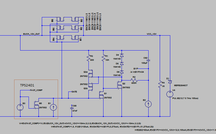
Here's circuit we've simulated that seems to do what we want (it's being implemented in hardware now) - but I wanted to get this out there for comments and or constructive suggestions on how to better achieve the transitions (BBU turn off is handled by lowering the output set point until the PSUs ramp up current and the ORing FET becomes reverse biased.)