This thread has been locked.

If you have a related question, please click the "Ask a related question" button in the top right corner. The newly created question will be automatically linked to this question.

Issue with TPS54040ADGQR EMC compliance

Other Parts Discussed in Thread: TPS54040A, TPS54140, TPS54040

We are using the following circuit with the TPS54040ADGQR and it is working well for us:

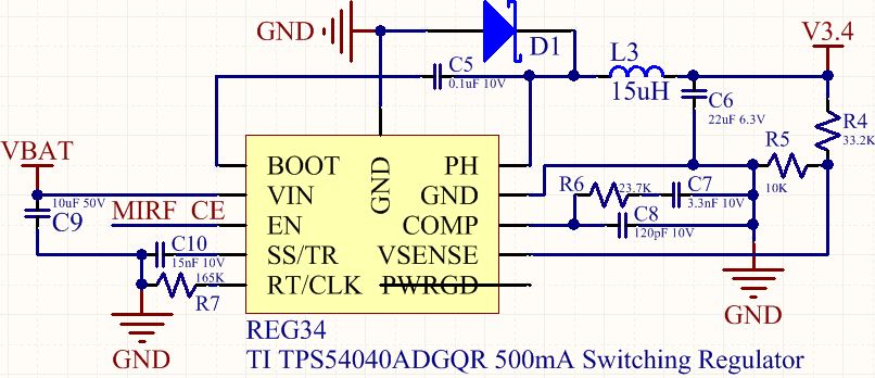
The inductor is TDK VLCF4028T-150MR88-2, and the diode is ON Semi MBRA340T3G; output capacitor is a standard X5R 0805 22uF, and input capacitor is a standard X5R 1206 10uF.  Target frequency is 700kHz.

This works fine with our GPS and other sensitive circuits, however we are having EMC compliance issues.


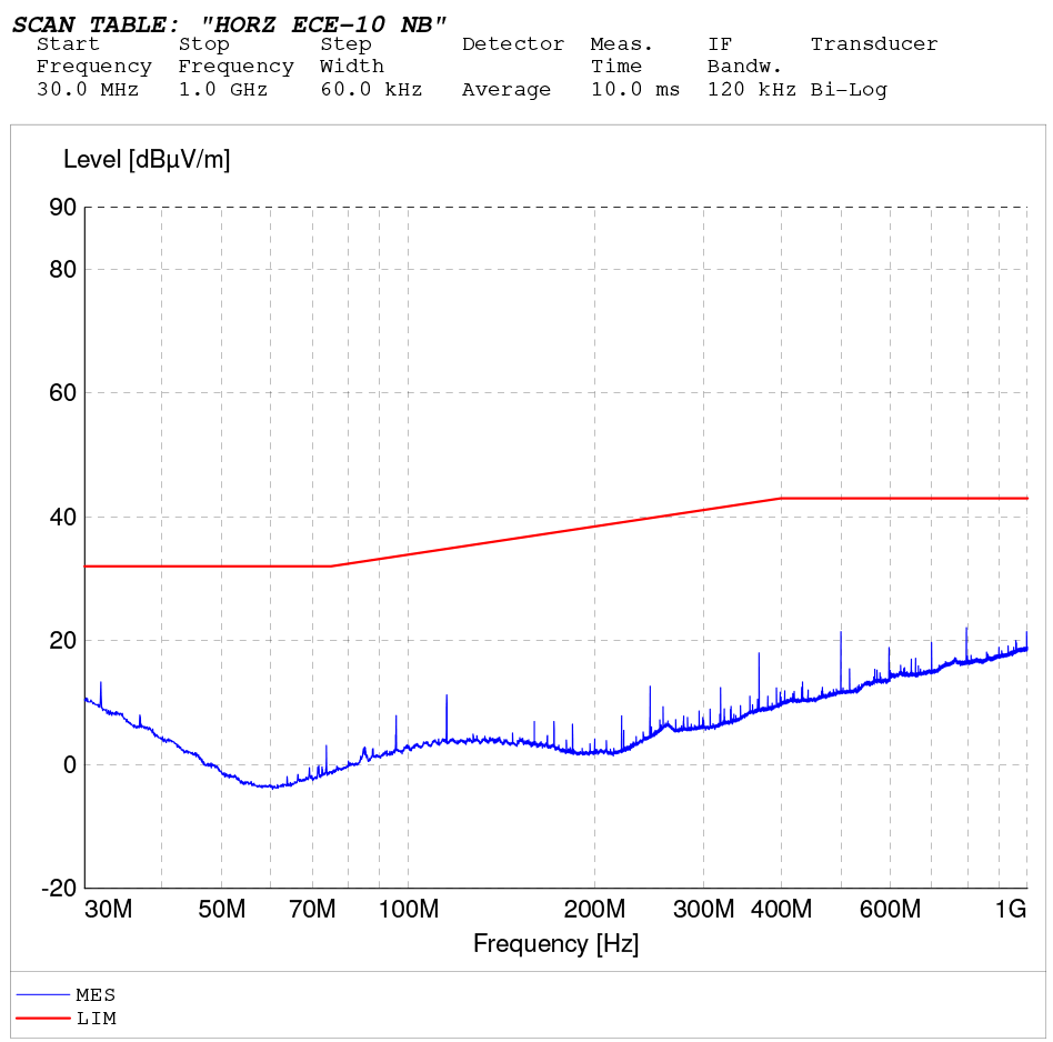
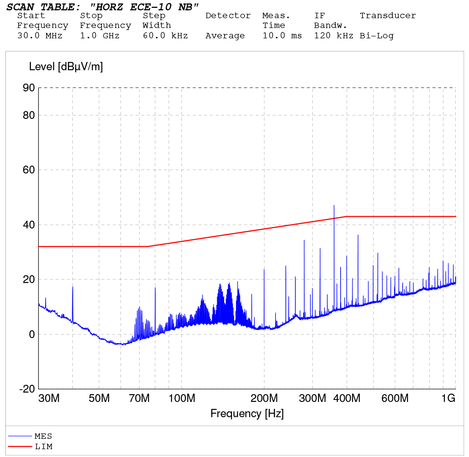
Here are the ECE Horizontal base/active plots:

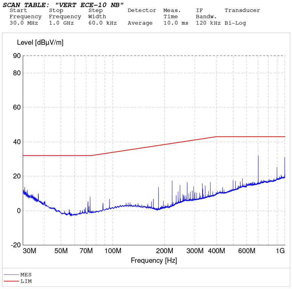
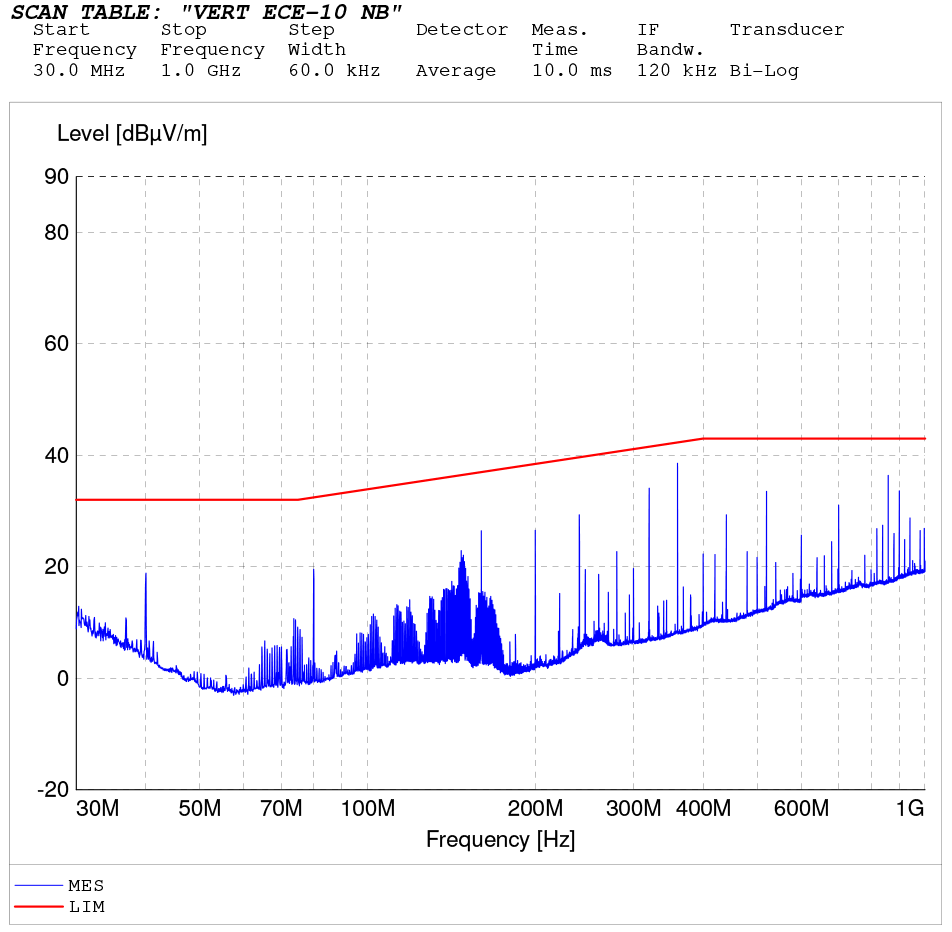
Here are the ECE Vertical base/active plots:

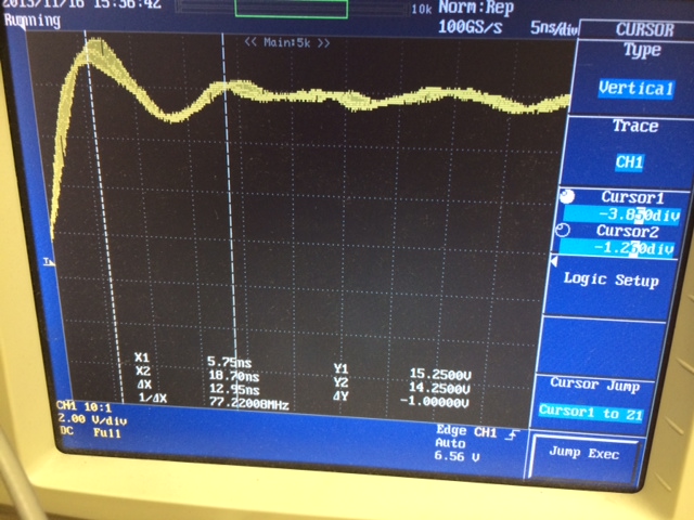
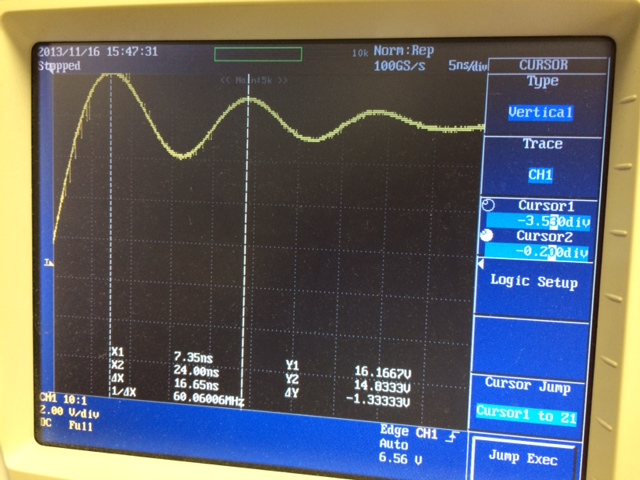
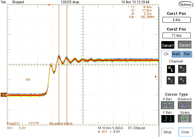
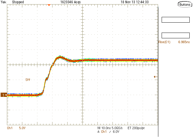
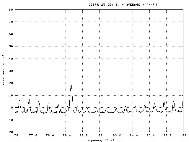
We are also seeing quite a bit of noise in the VHF low range (base/active):

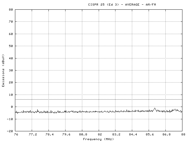
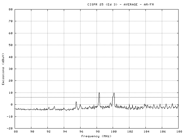
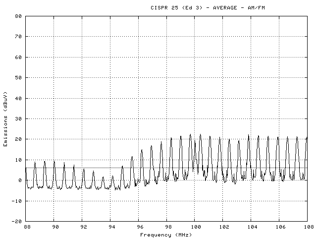
And the VHF high range (base/active):

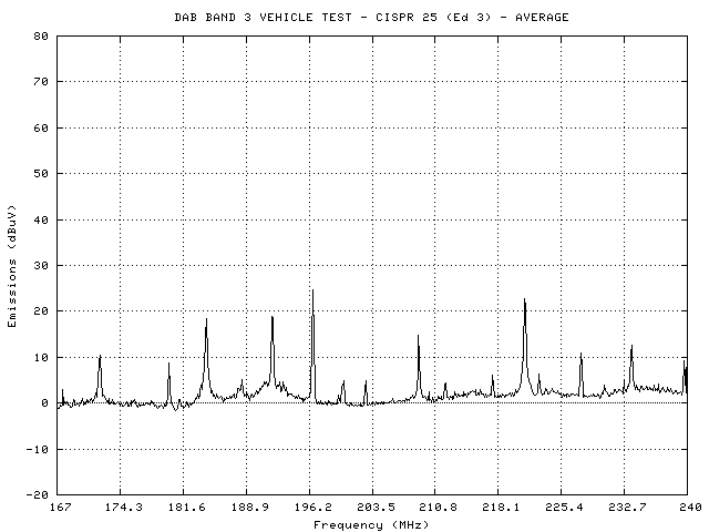
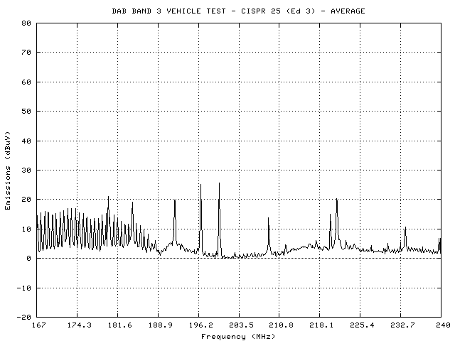
Finally, we are seeing some increase in baseline noise in the 167-240 MHz range (base/active):


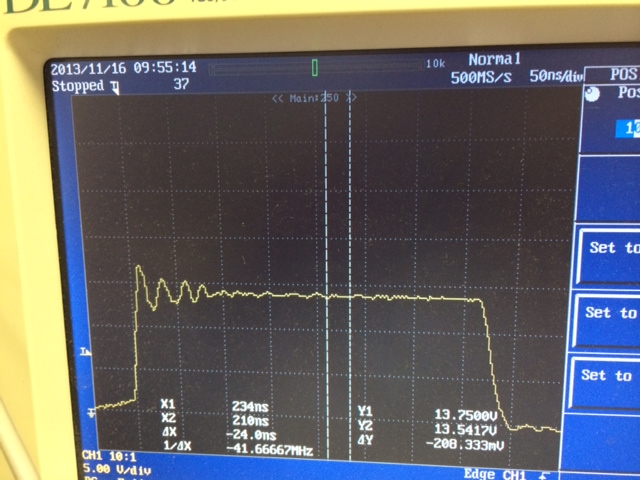
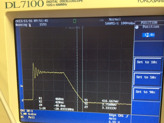
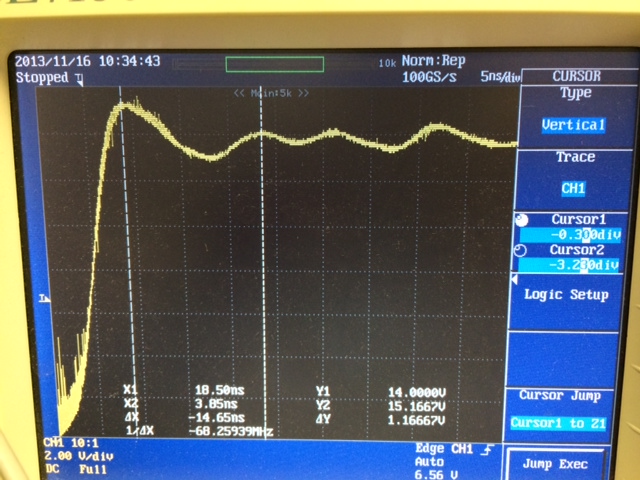
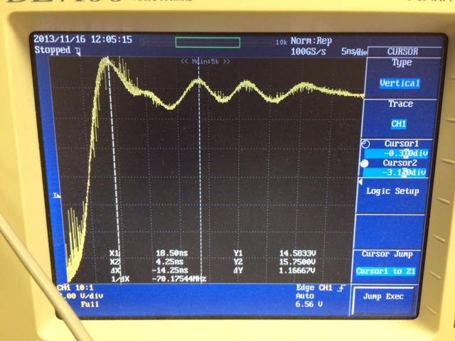
Does anyone have any suggestions regarding how to improve this situation?  The magnitude of the effect seems to be somewhat proportional to the output current.  Assuming I'm trying to change/add as few parts as possible, should I be looking for a different inductor, or some low-value capacitors, or adjusting the switching frequency?  Thanks for any input!

  • Hi Robert,

    First, thank you for the very detailed post! You're on the right track for what you can change here to limit the noise.

    Changing the frequency should not have very much impact. What I think will end up being most effective at limiting this high frequency noise is adding a snubber on the PH pin.

    I cannot make a specific recommendation on the inductor and diode, but changing these can of course change the noise. I'm curious, why was a 3A diode selected over say a 1A diode? A lower current diode may have better noise performance because it has lower capacitance.

    Adding the the low-value capacitor on the input can also help and I expect you will find something near 2200pF to work best for the VHF noise. If you try this, put it closer to the IC and D1 than the 10uF cap.

    Lastly, if you plan to redo the layout, I recommend moving the boot capacitor to the bottom side if you can. This creates a more solid GND connection between the input capacitors and the diode. If you can't put it on the bottom side, you could at least rotate it 90 degrees to allow a slightly thicker GND connection.

    Best Regards,
    Anthony 

  • Hi Anthony,

    Thanks for the detailed reply!  I am trying to sort out the snubber design; I couldn't find Coss for the IC, so I'm guessing around 60-170pF for similar NMOS FETs.  Am looking at http://www.newark.com/pdfs/techarticles/cornell/design.pdf which would indicate using a 390pF capacitor on the high end of this (can I use a ceramic 0402 for this?)

    This is the waveform I am seeing on PH:

    Am I taking the right approach here?  Or should I use this guide instead?

    http://www.ti.com/ww/en/analog/power_management/snubber_circuit_design.html

    For the diode, there was no particular reason except it was the only part I recognized on the part selector tool.  I am thinking of switching to PMEG6010CEH,115 which is a 60V rated Schottky 1A diode with 60pF of capacitance.  There is a 40V version PMEG4010CEH,115 as well with slightly lower Vf and 69pF capacitance, not sure if this is better or not?

    For the input capacitor, in addition to the 2200pF capacitor, should I include a 1000pF capacitor to handle the DAB Band?  Should I also include something a bit higher, maybe 4700pF, just in case?

    I put the boot capacitor on the same layer to keep it away from the GPS antenna layer lest it contribute noise.  I will attempt to improve the grounding on the next spin, thanks.

    I think I'm golden once I sort out this snubber circuit.  Any thoughts greatly appreciated.  Thanks!

  • is this problem is resolved.. the layout is not clear to me...

  • Hi Robert,

    For the snubber, that is the right approach in general. The example in the link you gave is for a boost, so the capacitance of the internal FET actually won't be on the switching node. In a buck it would be the reverse biased diode capacitance. I recommend the TI link you show instead though since it will account for any other capacitance on the PH node in the real application. You also have the right approach to measure the frequency of the ringing.

    For the diode, the PMEG6010CEH has a good chance to give you better performance. If you can do comparison measurements in performance it would be best in my opinion so you can actually see the difference. Do you have your own equipment for these measurements or have you been paying for time at a location with the full setup (anechoic chamber, etc.)?

    For the input capacitor, be careful about using caps near the same values. It can cause some resonance and reduce the effectiveness of both. I try to keep the capacitor values a decade apart.

    Best Regards,
    Anthony 

  • Hi Anthony,

    I attempted the first step of the TI guide and tried to find a resistor value that changed the oscillation frequency.  Below is the oscillation with no capacitor from PH to Ground:

    And this is with 2.2nF from PH to Ground:

    I am not seeing a frequency change in the ringing on the front end.  Am I missing something?  I tried a variety of values from 220pF to 680pF as well.

    Thanks!

  • Are you measuring the ringing with a very short GND lead? If not there could be inductive coupling interfering with the measurement. Typically I wrap a short wire around the barrel of the scope to provide a very short ground lead.

  • Hi Anthony,

    Ok, now I am seeing (no capacitance added yet):

    Does this look more reasonable?

    Thanks!

  • And this is with 120pF added between PH and Ground:

  • Hi Anthony,

    I was seeing some pretty small impacts from adding 560pF capacitors with the MBRA340 diode (which looks like it has a capacitance of between 300 and 1000pF), so I switched to an MBR0540 (which looks like 18-90pF).

    Here is the plot with no capacitors with the new diode:

    With one 560pF capacitor installed from PH to Ground:

    With 2 560pF capacitors installed from PH to Ground:

    With 6 560pF capacitors installed from PH to Ground (this is about half the frequency):

    Sanity check, with one 2.2nF capacitor installed from PH to Ground:

    So from this I am calculating Cext = 3300pF, so Cs = 1100pF

    This gives me an Ls = 3.5nH

    Csnub >= 5500pF

    Rsnub = 0.9ohm

    Does this sound at all reasonable or am I doing something stupid?  Thanks!

  • Ok, in my impatience I rigged up the nearest values I had and tried it out (1 ohm 0402 and 6.8nF 0805).

    Here is the original circuit behavior zoomed-out:

    Here is the new circuit behavior zoomed-out:

    Here is the original circuit behavior zoomed-in:

    Here is the new circuit behavior zoomed-in:

    I couldn't find an FFT function on my scope (sure it's hiding somewhere), but I suppose this looks better to me...  Is this what I should be expecting?

    Thanks!

  • Hi Robert,

    The recent screenshots look more like what I expected. The resistor is a bit smaller and the capacitor is a bit larger than I usually need. Also the ring doesn't look reduced too much but the slower rise time on the switching signal will definitely help to reduce high frequency noise.

    I haven't put a snubber on the TPS54040A specifically before so I'm going to check it out on Monday for a quick sanity check.

    Best Regards,
    Anthony 

  • Robert,

    I tested out a snubber on the TPS54140 EVM. I didn't have any TPS54040 EVMs, but the performance should be almost identical. I found that the closest standard values for the snubber were 3.9 ohms and 560 pF.

    Screenshot before snubber:

    Screenshot after snubber:

    Anthony

  • What load current are you testing with? I tested with 500mA.

  • Hi Anthony,

    Thanks.  I was testing at 40mA.  Do you think the diode on your EVB is equivalent enough to the MBR0540 that I can use your values?  Thanks!

  • My values should work ok however the B260 diode on the EVB has a bit more capacitance. The measurements show the switch node capacitance to be very close to the capacitance on the diode's datasheet. My measurements were about 110pF capacitance and 6.3nH of inductance. Assuming the inductance doesn't change and the capacitance of the MBR0540 diode is 30pF, the values come out to Csnub  = 150pF and Rsnub = 7.25 ohm.