


Hello EveryBody,
I am using TPS62143, I just want to know, if I connect SW1 SW2 and SW3 together!! Or must I seperate them "I connect Vin only on SW1"?!!
Please help me!!
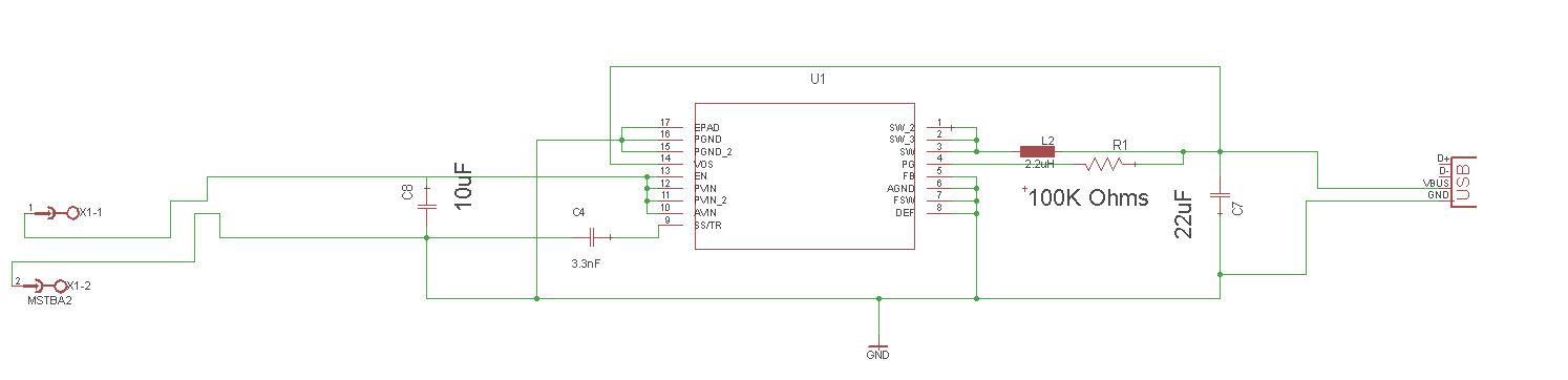
Here my schematic!!
Hello EveryBody,
I am using TPS62143, I just want to know, if I connect SW1 SW2 and SW3 together!! Or must I seperate them "I connect Vin only on SW1"?!!
Please help me!!
Here my schematic!!


