This thread has been locked.

If you have a related question, please click the "Ask a related question" button in the top right corner. The newly created question will be automatically linked to this question.

BQ24070 battery low, Q2 = BATT?

Other Parts Discussed in Thread: BQ24070

Hello,

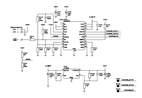
We are using the BQ24070 to charge a 3500mAh Li-ion battery and to drive a board with uC, GPS and GSM modules.

1. When only battery is connected, what is supposed to happen on the output when battery gets really low? If Q2 = BATT in this condition, it means that the output always shall equal the battery voltage? But when measuring the battery (UN3480), it is 3.84V, but the output of the BQ24070 is sometimes 1.61V. Is this a designed way to protect the battery for avoiding deep discharge? The thing is that when inserting supply voltage at that state, the voltage ramp for the components will be from 1.6V and not from 0 volts. Can you explain this behaviour? Note that if taking out the battery and replacing the connector again, the OUT pin is correct again, i.e. 3.84V / battery voltage. EDIT: when reading other posts this really sonds like the short-circuit detection state".

2.The peak current of the GSM module is 2A. We measure drops of 0.2V from the output (from 4.4V to 4.2V) when the GSM is active sending. Is this normal? Can I redesign to avoid this? 

  • Here is a possible theory of my observations.

    After production, the last thing we do before shipping is to connect the battery (when there is no other power supplies).

    For some percent of the produced units, the short-circuit detection seems to have occured (even there is no short), and the board looks dead because no components have started, because the OUT pin is too low (about 1.6V). 

    Question: If a short-circuit is detected, is it possible that the output is about 1.6V? How can I verify that a short-circuit is detected? How can I avoid short-circuit detection (because there is no short-circuit). Should I have a capacitor on the DPPM output pin? I see some short-circuit recovery options in the data sheet, but I am not sure if it is a short-circuit detection state. 

    Question2: When the unit is operating normally on battery only and gives out 4.4V, will the OUT-pin follow the battery discharge curve to 0V?

    Question3: It is critical for my design that the power up ramp from 0V-3V (output of U101) is within 10ms. But if the BQ24070 sometimes is locked at 1.6V, the ramp will go from 1.6V to 3V when the main supply voltage is connected and the units (i.e.GPS module firmware) will freeze. So do you have any design change recommendations to always ensure stable voltage power up ramp. Also for the case where the battery is going low and suddenly the main power supply is connected and the power up ramp will be from any voltage between [0-3]V and 3V.

    Please help me out here!

  • Dear Texas Instruments,

    Could you recommend a switch/circuit between the output of the BQ24070 and the board (the load). The purpose is to protect the battery and to have a reset switch opportunity for the load.

    It should have two inputs:

    Input1: input from micro controller (floating/low: power to the load, active high: see spec below)

    input2: detecting mains supply voltage. If mains power: power to the load

    When the board is working on battery power only it is possible to measure the battery voltage with a divider. So if the battery is below, say 3.2V, the Input 1 is driven high. This should then have two outfalls:

    - If Input2 is high (mains power), then the circuit should only be reset for some seconds, i.e. switch output low for say 10 seconds.

    - If input2 is low (no mains power) the switch should not give output until input2 is high again.

    I guess the requirements above are not new to you guys,

    If the design should be otherwise, please tell.

  • I have not been able to recreate the 1.6V clamp on OUT.  It could be a hot plug issue where there is ringing at battery connect that is tripping the short circuit protection circuitry.  Changing the capacitors on BAT or OUT may help. Or we may need a tuned resistor and capacitor on BAT to snub the ringing.  To know for sure, I would need to see a scope capture of BAT and OUT at the moment this occurs.

  • If the OUT capacitance is large, when the battery is attached, the in rush current to charge that capacitance causes the short circuit current protection to trip.  This turns off the battery FET, leaving only a leakage path to charge OUT up to 1.6V max.  You can increase the capacitance on the DPPM to slow down the response time of the short circuit protection.