This thread has been locked.

If you have a related question, please click the "Ask a related question" button in the top right corner. The newly created question will be automatically linked to this question.

Adjustable negative supply with LM2576HV-ADJ

Other Parts Discussed in Thread: LM2576HV, LM2576

Hello,

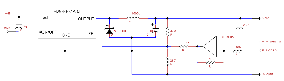
I'm currently designing a adjustable supply for a power op-amp with a digitally adjustable output. The output will be regulated with a DAC and fed in via an op-amp to the reference pin. I designed a separate positive and negative rail with each a LM2576HV-ADJ. The positive rail for the op-amp wasn't a problem, but the negative rail causes trouble. I build the circuit as in the following figure LINK. The component values are the same as for the positive rail. When I turn the power the current rises and the output voltage doesn't reach the expected value of -35V. Are the components wrong or is there anything else I can to to make this converter work.

Thanks in advance.

  • Hi Egbert,

    The reason for the difficulty is because the reference feedback pin is tied to the negative Vout rail.

    We've attached a schematic that should lead you to a workable solution. In this application, a conventional feedback divider establishes max output voltage of 35V.

    6521.E2E - Negative output design - Egbert.pdf

    Thanks,

    Anston

  • Hi Anston,

    Thanks for your reply, I will take a look at it.
    I do have still two questions, the datasheet shows me that for a negative supply of -12V the maximum input voltage is 48V. When I apply 48V to the input and regulating to -35V there is a Voltage difference of 83V. Would this be a problem for the LM2576HV?

    "Also, the maximum voltage appearing across the regulator is the absolute sum of the input and output voltage.For a −12V output, the maximum input voltage for the LM2576 is +28V, or +48V for the LM2576HV."

    The other question is about the inductor used in both circuits, I have used a 1500uH inductor based on the calculations of the adjustable example, but the specs show me that an inductor with a value between 68uH and 220uH must be used. Is my inductor too large for this goal?

    "The recommended range of inductor values for the buck-boost design is between 68 μH and 220 μH, and the output capacitor values must be larger than what is normally required for buck designs. Low input voltages or high output currents require a large value output capacitor (in the thousands of micro Farads)."

    Thanks in advance,

    Egbert

  • Hi Egbert,

    You are correct that from +48V to -35V, the potential difference is 83V and would violate recommended Abs Max of the device. 

    In this topology, the inductor current is the sum of the input and output currents. Inductor current can be roughly estimated as follows,

    Ind_current= Iout + ((Pout(Max)/Vin)*1.1)

    Thanks,

    Anston