


We are using TPS65910AA1 to power AM3352BZCZD60 microprocessor and we are facing problems with ripple levels in the step-down converters connected to Core Supply Voltages. These ripple levels are greater than tolerances established in MPU datasheet (44 mV to VDD_CORE and 48 mV to VDD_MPU).
The figures bellow show ripple measured at VDD_CORE decoupling capacitor (Channel 01) and VDD2 SMPS switching node (Channel 03).
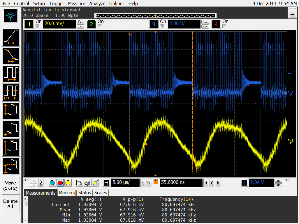
Figure 01
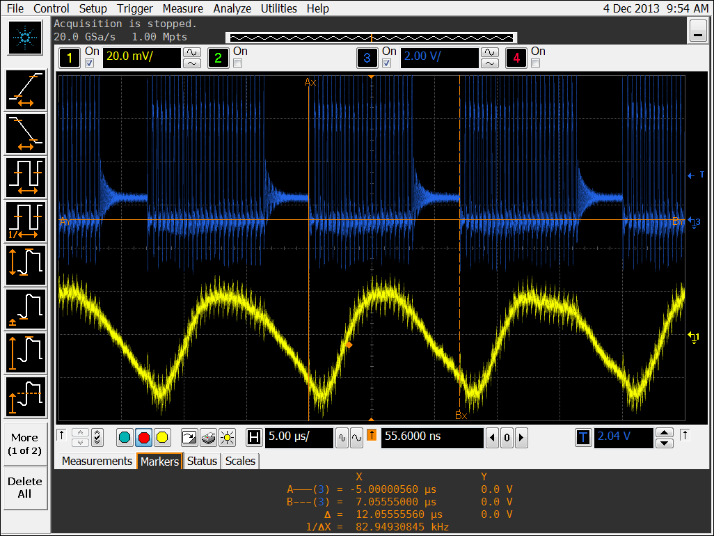
Figure 02
Probably, this supply is in PFM mode but we do not find a detailed discussion of this low-power mode in PMIC datasheet. Could someone help me with the following questions?
1) What are the conditions to enter this low-power mode? Is it possible to turn off this feature?
2) Are the frequencies measured in Figures 01 and 02 related?
3) Would ripple be different if the switching node were continuous?
4) We are using a 10uF capacitor for SMPS LC Filter and the decoupling capacitors mentioned in MPU datasheet (1 cap of 10 uF and 8 caps of 10 nF). This association exceeds the maximum value of 12 uF established in PMIC datasheet to filter capacitor Co(VDD2). What kind of problems can we face exceeding this parameter?
