


Hi,
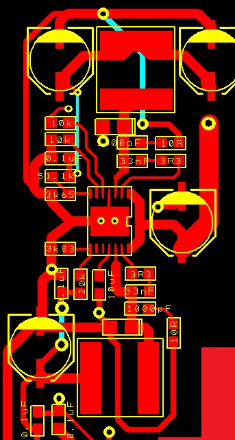
I have copied the suggested design in the datasheet of TPS54286 for 24v-to-5v&12V@2A as I have attached. I have attached the PCB too.
The problem is the output is 24V on Side 2. Side one is zero. This behavior has been repeated similarly 5 times, like one of them gets to 24v , and burns the switch and causes a short circuit afterwards. If I replace it, happens again.
1- I think I don't have short circuits anywhere or soldering problem, . I have a reasonable 330-ohm in the output of both sides. I have attached the GND pad beneath. both enable pins are connected or pulled down to GND by a 10k resistor. at all times. Switch output also is always 24V on side 2 and 0V on side 1. FB on side one is 1.5V
Sometimes the chip immediately burns last time that I tried to be super careful, it didn't burn but gets hot. I have no other component in the circuit
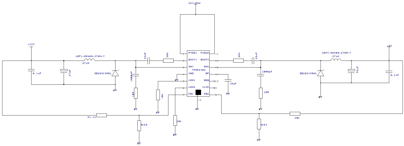
The only difference is the inductor I chose and the diode.
Link to inductor:
http://www.digikey.com/product-detail/en/ASPI-8040S-270M-T/ASPI-8040S-270M-TCT-ND/3060414
Link to diode
http://www.digikey.com/product-detail/en/DB2W31900L/DB2W31900LCT-ND/2704454
Any guess out of your vast experience is really welcome.
Regards